Does this sound familiar? A new module enters the market and your first thought is: Oh, I know that one, I already have one of these, two in one housing – so what…
I’ll take another look anyway: Oh, morphing between filter types, even via CV. Lots of control inputs, common for both filters, separate for both filters. 5 CV inputs just for the cutoff-frequencies, no, even 6 if you count Δ FM. Some things are conceptually reminiscent of the poly modules, only for 2 instead of 4 voices. However, the module is not limited to “2-voice synths”, stereo is suitable, as is parallel or serial filtering. There are actually a lot of features built into this thing that you don’t get with two “normal” A-121 modules and that would require a whole bunch of additional amplifiers / crossfaders etc. that would cost significantly more and require significantly more space.
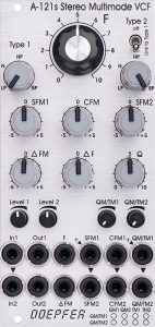
Speaking of space: The module basically follows the design of the new “Slim Line” modules: Smaller potentiometer knobs, some with narrow potentiometer axes as rotary controllers, controls at the top – sockets at the bottom, but it also has a fat retro controller at the top in the middle, which is responsible for setting the cutoff-frequencies of both filters together.
Overview of the module
Yes, this is actually one of the modules that you should first get an overview of. However, it is far less complex than one might infer from some reports online.
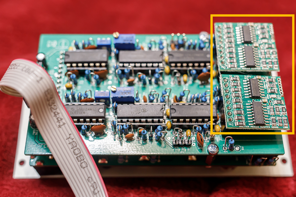
We have two 12dB multimode filters, which technically correspond to the A-121-2 or its “slimline brother” A-121-3. Instead of the four individual outputs for the filter types (low pass, high pass, notch and band pass), Doepfer has given the A-121s a small morphing unit for each of the two filters, which crossfades between the types as required. By the way, the morphing units sit as two small, separate boards piggybacked on Board A of the module.
Manual control
To control the module, the first thing that catches the eye is the large “F” controller in its retro design: Here we set the cutoff-frequency for both filters at the same time.
Then there is a “Type” control for each filter, which can smoothly fade between the filter types. If necessary, you can deactivate the second controller: “Type 1” then controls the filter type for both filters at the same time. A “Q” control is responsible for the feedback of both filters (together), with “Δ F” you can finally move apart (“spread”) the cutoff-frequencies of both filters symmetrically. And if we haven’t patched any external modulation sources into the two “SFM” inputs, then we can still set the cutoff-frequency of each of the two filters manually using the two “SFM” controls – starting from the basic setting using the fat retro control “F” at the top.
So far it’s not rocket science, it’s pretty straightforward.
Modulation options
Here, too, nothing that you don’t already know from many other filters: an “F” input (without attenuator) with which you can modulate the cutoff-frequencies of both filters together (analogous to the large “F” control). Another control voltage input “Δ FM” allows the spread of the cutoff-frequencies to be modulated externally. We have a polarizer “Δ FM” to make this positive or negative.
In addition, for each of the two filters there are two separate modulation inputs “SFM” and “CFM” for the individual cutoff-frequencies. What is the difference? The two “SFM” inputs each have their own polarizer (“SFM1” and “SFM2”), the two “CFM” inputs are controlled by a common polarizer “CFM”.
With the polarizers you can completely disable the external modulation sources (controller position “0”) or control them positively (clockwise to the right of “0”) or inverted (counterclockwise to the left of “0”). The inversion of control voltages is particularly interesting for envelope signals, especially if the ADSR generator does not have an inverted output.
Is the common “CFM” polarizer now a savings version and a compromise because there was no more space on the panel? No, on the contrary, it is often even desirable that two modulation sources have as similar an effect as possible on the filters, e.g. if you play duophonic and the envelopes of both voices should have the same effect (but separately in time) on the course of the two cutoff-frequencies. We find a similar concept in the four-voice A-105-4 and its four “FM” inputs with the common “FM” control.
As a fan of the polyphony in the A-100, I’ll discuss how two A-121s can be used in a four-part polyphonic setup.
So, the simulation options aren’t terribly complicated either. Now only two inputs “QM/TM1” and “QM/TM2” are missing, each with a simple attenuator. They’re actually “a little” more complicated to understand, but experienced modular users aren’t afraid of ANYTHING, right?
The QM/TM thingies and how to deal with them
The module has a total of 8 modulation inputs. Two of them – “QM/TM1” and “QM/TM2” – are a headache at first because they can also be configured using a number of jumpers. Basically these two inputs are responsible for:
- the modulation of the resonance (“Q”) and/or
- morphing between the filter types (lowpass, notch, highpass and bandpass).
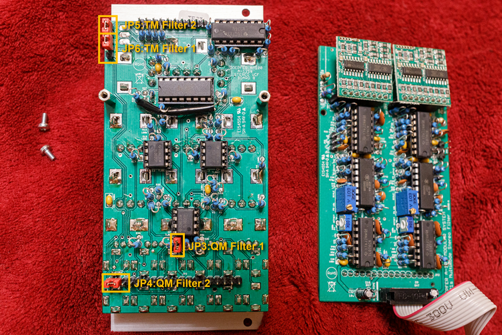
And the whole thing for two filter units built into the module. This gives us four possible modulation destinations and two modulation sources (inputs). The good news: The assignment of the inputs to the modulation targets can be freely determined using jumpers. The bad news: You first have to decide what you want. It’s not a “forever” decision, but to make changes you have to remove the module, unscrew the upper circuit board, set the jumpers specifically, screw the upper circuit board back on and install the module back into the rack.
The jumpers for the modulations are intended for the modulation goal: Each of the four modulation targets has its own jumper, which can completely remove the target from the modulation (jumper removed), or specify the source or one of two sources.
What options do we have?
| Modulation target: | Jumper: | Modulation source: | Jumper position: |
|---|---|---|---|
| Resonance of filter 1 | JP3 | QM/TM1 (without) | plugged in removed |
| Resonance of filter 2 | JP4 | QM/TM1 QM/TM2 (without) | left right removed |
| Type of filter 1 | JP6 | QM/TM1 QM/TM2 (without) | bottom top removed |
| Type of filter 2 | JP5 | QM/TM2 (without) | plugged in removed |
What do you notice? Not all modulation targets can be controlled by all sources (or modulation inputs)!
- For example, there is no way to modulate the resonance of Filter 1 via the QM/TM2 input. Likewise, we cannot have the type of filter 2 modulated via the QM/TM1 input. But since both filters are identical, they can be interchanged if necessary, so we don’t have any real restrictions.
- There is no way to control a modulation target via two different modulation inputs at the same time. So if you want to use multiple modulation sources (LFOs, ADSR, etc.) for the same target, you will use a small linear mixer for these sources.
If you take a closer look at the table above, there are theoretically 36 different ways to control the modulation of the resonances and filter types via the two inputs (there are 2 x 3 x 3 x 2 different ways to set the jumpers). Of course, not all combinations are equally useful in practical use, e.g. you can of course save yourself the setup in which all jumpers are removed: the two inputs would then be completely without function.
Let’s take a closer look at these modulation connections. I marked the links that I think are particularly useful in bold, and those that are irrelevant in practice in light gray. For me, all setups in which one (or even both) modulation inputs have no function are “irrelevant”.
| Setup Nr.: | Modulation connections: | JP3: | JP4: | JP5: | JP6: |
|---|---|---|---|---|---|
| 1 | QM/TM1: Resonance of both filters, type of filter 1 QM/TM2: Type of filter 2 | plugged in | left | plugged in | bottom |
| 2 | QM/TM1: Resonance of both filters QM/TM2: Type of both filters DEFAULT factory setting | plugged in | left | plugged in | top |
| 3 | QM/TM1: Resonance of both filters QM/TM2: Type of filter 2 | plugged in | left | plugged in | removed |
| 4 | QM/TM1: Resonance of both filters, type of filter 1 QM/TM2: WITHOUT FUNCTION | plugged in | left | removed | bottom |
| 5 | QM/TM1: Resonance of both filters QM/TM2: Type of filter 1 | plugged in | left | removed | top |
| 6 | QM/TM1: Resonance of both filters QM/TM2: WITHOUT FUNCTION | plugged in | left | removed | removed |
| 7 | QM/TM1: Resonance & type of filter 1 QM/TM2: Resonance & type of filter 2 | plugged in | right | plugged in | bottom |
| 8 | QM/TM1: Resonance of filter 1 QM/TM2: Resonance of filter 2, type of both filters | plugged in | right | plugged in | top |
| 9 | QM/TM1: Resonance of filter 1 QM/TM2: Resonance & type of filter 2 | plugged in | right | plugged in | removed |
| 10 | QM/TM1: Resonance & type of filter 1 QM/TM2: Resonance of filter 2 | plugged in | right | removed | bottom |
| 11 | QM/TM1: Resonance of filter 1 QM/TM2: Resonance of filter 2, type of filter 1 | plugged in | right | removed | top |
| 12 | QM/TM1: Resonance of filter 1 QM/TM2: Resonance of filter 2 | plugged in | right | removed | removed |
| 13 | QM/TM1: Resonance & type of filter 1 QM/TM2: Type of filter 2 | plugged in | removed | plugged in | bottom |
| 14 | QM/TM1: Resonance of filter 1 QM/TM2: Type of both filters | plugged in | removed | plugged in | top |
| 15 | QM/TM1: Resonance of filter 1 QM/TM2: Type of filter 2 | plugged in | removed | plugged in | removed |
| 16 | QM/TM1: Resonance & type of filter 1 QM/TM2: WITHOUT FUNCTION | plugged in | removed | removed | bottom |
| 17 | QM/TM1: Resonance of filter 1 QM/TM2: Type of filter 1 | plugged in | removed | removed | top |
| 18 | QM/TM1: Resonance of filter 1 QM/TM2: WITHOUT FUNCTION | plugged in | removed | removed | removed |
| 19 | QM/TM1: Resonance of filter 2, type of filter 1 QM/TM2: Type of filter 2 | removed | left | plugged in | bottom |
| 20 | QM/TM1: Resonance of filter 2 QM/TM2: Type of both filters | removed | left | plugged in | top |
| 21 | QM/TM1: Resonance of filter 2 QM/TM2: Type of filter 2 | removed | left | plugged in | removed |
| 22 | QM/TM1: Resonance of filter 2, type of filter 1 QM/TM2: WITHOUT FUNCTION | removed | left | removed | bottom |
| 23 | QM/TM1: Resonance of filter 2 QM/TM2: Type of filter 1 | removed | left | removed | top |
| 24 | QM/TM1: Resonance of filter 2 QM/TM2: WITHOUT FUNCTION | removed | left | removed | removed |
| 25 | QM/TM1: Type of filter 1 QM/TM2: Resonance & type of filter 2 | removed | right | plugged in | bottom |
| 26 | QM/TM1: WITHOUT FUNCTION QM/TM2: Resonance of filter 2, type of both filters | removed | right | plugged in | top |
| 27 | QM/TM1: WITHOUT FUNCTION QM/TM2: Resonance & type of filter 2 | removed | right | plugged in | removed |
| 28 | QM/TM1: Type of filter 1 QM/TM2: Resonance of filter 2 | removed | right | removed | bottom |
| 29 | QM/TM1: WITHOUT FUNCTION QM/TM2: Resonance of filter 2, type of filter 1 | removed | right | removed | top |
| 30 | QM/TM1: WITHOUT FUNCTION QM/TM2: Resonance of filter 2 | removed | right | removed | removed |
| 31 | QM/TM1: Type of filter 1 QM/TM2: Type of filter 2 | removed | removed | plugged in | bottom |
| 32 | QM/TM1: WITHOUT FUNCTION QM/TM2: Type of both filters | removed | removed | plugged in | top |
| 33 | QM/TM1: WITHOUT FUNCTION QM/TM2: Type of filter 2 | removed | removed | plugged in | removed |
| 34 | QM/TM1: Type of filter 1 QM/TM2: WITHOUT FUNCTION | removed | removed | removed | bottom |
| 35 | QM/TM1: WITHOUT FUNCTION QM/TM2: Type of filter 1 | removed | removed | removed | top |
| 36 | QM/TM1: WITHOUT FUNCTION QM/TM2: WITHOUT FUNCTION | removed | removed | removed | removed |
This gives us 21 basically useful setups through the jumpers, 9 of which are quite practical in my opinion, even if they are partially redundant: Some setups only differ in the assignment of the two – identically constructed – modulation inputs or the two – identically constructed – filters. If we “condense” this a little further, then we essentially have the following six options:
| Modulation connections (summarized): | Setup Nr.: |
|---|---|
| One input modulates the resonance of both filters, the other input modulates the type of both filters. This is very practical if you want both filters to behave as equally as possible, e.g. in a duophonic or 4-voice setup (then with 2 A-121s modules). Then global controls such as the aftertouch would modulate the resonance and the modulation wheel would modulate the type of both filters. DEFAULT setup from the factory. | 2 |
| One input modulates resonance and type of one filter, the other input modulates the resonance and type of the other filter. A bit “exotic”, admittedly. We couple type and resonance (LP has no resonance, BP has maximum resonance), but we get maximum sound change through the modulation. The filters are completely independent of each other. | 7 |
| One input modulates the resonance of one filter, the other input modulates the resonance of the other filter. Here too, the filters are completely independent of each other. We restrict ourselves conservatively to modulating the resonance of both filters. In a duophonic/polyphonic setup, for example, note-specific parameters such as the pitch played or velocity dynamics could control the resonances of the filters separately. | 12 |
| One input modulates the type of one filter, the other input modulates the type of the other filter. Here too, the filters are completely independent of each other. We restrict ourselves conservatively to the modulation of the filter types. Again, note-specific parameters (pitch, velocity) could separately control the types of filters in a duophonic/polyphonic setup. | 31 |
| One input modulates the resonance of one filter, the other input modulates the type of the other filter. Here the filters are not only independent of each other, but also have different “features” – one filter can be modulated in resonance, the other in type. This can be interesting for serial filtering, for example. | 15, 23, 28 |
| One input modulates the resonance of one filter, the other input modulates the type of the same filter, the other filter is not modulated. Independence of the filters is taken a little further: One filter can be modulated (differently) in both resonance and type, the second filter does not have these “features” and is operated purely manually in terms of resonance and type. However, manually adjusting the resonance always affects both filters at the same time. | 17, 21 |
This was – admittedly – more “preliminary banter” than with most other modules, but everything remains completely logical and clear at all times. Many possibilities in a very small space require that you first take a closer look…
Polarizer, preset voltages and basic setting
The module has a total of five polarizers: “SFM1”, “CFM”, “SFM2”, “Δ FM” and “Δ F”. If you are looking for a neutral starting position to adjust the filters as needed, it is a good idea to initially set all four polarizers to “0”. The two “SFM” controllers are particularly important because they are always provided with a constant control voltage, even without external modulation sources.
You should also initially set the two small attenuators “QM/TM1” and “QM/TM2” to zero – they also have a constant control voltage, which – depending on the configuration of the jumpers on the circuit board – can have various effects on resonance and filter type.
User interface
Inputs:
On some inputs, a downward-pointing triangle is drawn between the upper and lower sockets: Here the lower input is a switching socket that is pre-assigned with the signal from the upper input.
Next to two sockets (“SFM1” and “QM/TM1”) there is a “+” with a small arrowhead drawn diagonally to the bottom right: These are also switching sockets, they are pre-assigned with a positive constant voltage.
The modulation inputs “QM/TM1” and “QM/TM2”, which can be configured in a relatively complex manner, have already been described in detail in the section above.
- In1: Audio input for filter 1. The “Level 1” controller is the attenuator for this input.
- In2: Audio input for filter 2. The input is a switching socket that is pre-assigned with the input signal from “In1”. Without a plug in “In2”, the input signal from “In1” is sent to both filters in parallel. The “Level 2” controller is the attenuator for this input.
- F: Control voltage input for joint control of the cutoff-frequencies of both filters. The input has no attenuator and is designed for approximately 1V/octave.
- Δ FM: Control voltage input to spread apart the cutoff-frequencies of both filters. If the voltage is positive, the cutoff-frequency of filter 1 is increased and that of filter 2 is decreased. The polarizer “Δ FM” controls the intensity and polarity of this input.
- SFM1: (“Single FM 1”) Control voltage input for the cutoff-frequency of filter 1. Without a plug, this switching socket is pre-assigned with a constant positive voltage. The polarizer “SFM1” controls the intensity and polarity of this input.
- SFM2: (“Single FM 2”) Control voltage input for the cutoff-frequency of filter 2. Otherwise it is similar to the input “SFM1”. The switching socket is pre-assigned with the voltage at “SFM1”. This is either an external control voltage or (without a plug in “SFM1”) the preassigned, constant voltage from “SFM1”.
- CFM1: (“Common FM 1”) Control voltage input for the cutoff-frequency of filter 1, analogous to “SFM1”, but without a pre-assigned voltage at the input. A common polarizer “CFM” regulates the intensity and polarity for both inputs “CFM1” and “CFM2” at the same time.
- CFM2: (“Common FM 2”) Control voltage input for the corner frequency of filter 2, otherwise like “CFM1”. The switching socket is pre-assigned with the control voltage at “CFM1”.
- QM/TM1: Configurable modulation input for resonance and/or type (morphing) of filter 1 and/or filter 2. The input has an attenuator “QM/TM1”. The switching socket is pre-assigned with a constant voltage.
- QM/TM2: Analogous to “QM/TM1”, with attenuator “QM/TM2”.
Outputs:
- Out1: Audio output from filter 1.
- Out2: Audio output from filter 2.
(That was almost too easy, wasn’t it?)
Controls:
- F: The fat retro button controls the cutoff-frequencies of both filters simultaneously.
- Link to Type 1: With this switch, the filter type can be set manually for both filters either separately (switch at the top, “off”) or together via the “LP-N-HP-BP” control for filter 1 (switch at the bottom, “on”).
- LP-N-HP-BP (Type 1): Manual controller for the type of filter 1. Continuous crossfading between lowpass (“LP”), notch (“N”), highpass (“HP”) and bandpass (“BP”).
- LP-N-HP-BP (Type 2): Analogous to the controller for filter 1, here for filter 2. If the “Link to Type 1” switch is set to “on”, this controller has no function. The filter types of both filters are then set together by the controller for filter 1.
- SFM1: Polarizer for the “SFM1” input (modulation of the cutoff-frequency of filter 1).
- CFM: Common polarizer for the two inputs “CFM1” and “CFM2” (modulation of the cutoff-frequencies of both filters).
- SFM2: Polarizer for the “SFM2” input (modulation of the cutoff-frequency of filter 2).
- Δ FM: Polarizer for the “Δ FM” input.
- Δ F: Manual controller for the spread of the cutoff-frequencies of the two filters. Clockwise from the center position “0” the cutoff-frequency of filter 1 increases and that of filter 2 decreases; counterclockwise from the center position it is the other way around.
- Q: Manual knob to control the feedback of both filters together.
- Level 1: Attenuator for the audio input “In1”.
- Level 2: Attenuator for the audio input “In2”.
- QM/TM1: Attenuator for the control voltage input “QM/TM1”.
- QM/TM2: Attenuator for the control voltage input “QM/TM2”.
Markers on the front panel
In order to make the somewhat complex assignment of “QM/TM” inputs to the modulation destinations visible on the front panel, a small modulation matrix with 8 circles is printed on it. Here you can – as a reminder – mark with a felt-tip pen how you have configured the module.
It makes sense to cover the panel at this point with a piece of transparent adhesive tape BEFORE making the markings. Maybe you want to use a completely different “QM/TM” configuration later…
Configuration via the board
With this module, the configuration options “under the hood” are limited to the modulation options of the two CV inputs “QM/TM1” and “QM/TM2”. As we saw at the beginning, going into the details here is already a full-length undertaking. To repeat again the effects of the four jumpers:
| Modulation target: | Jumper: | Modulation source: | Jumper position: |
|---|---|---|---|
| Resonance of filter 1 | JP3 | QM/TM1 (without) | plugged in removed |
| Resonance of filter 2 | JP4 | QM/TM1 QM/TM2 (without) | left right removed |
| Type of filter 1 | JP6 | QM/TM1 QM/TM2 (without) | bottom top removed |
| Type of filter 2 | JP5 | QM/TM2 (without) | plugged in removed |
Possible uses
A mono signal is processed in stereo
Clearly, with the spreading of the two filters – which can also be influenced by control voltage – stereo use is obvious. We can have a mono signal processed by both filters in parallel (“In2” is pre-assigned with the audio signal from “In1”), so we only patch our audio signal (e.g. a VCO) into the “In1” input.
We use both outputs “Out1” and “Out2” as outputs, then we continue, for example, via two VCAs and then distribute them as desired in the stereo image.
Beautiful stereo effects can be created from a simple mono signal by simply modulating the filter spreading via the CV input “Δ FM”. In order to avoid that only one side of the stereo image opens the filter to different degrees while the other stereo side closes its filter to different degrees, a modulation source is recommended that can generate both positive and negative control voltages. Most LFOs (triangle, sine, for example) can do this.
Stereo filter
For real stereo processing: Both inputs “In1” and “In2” are fed with different audio signals; we again use the outputs “Out1” and “Out2”.
The most interesting option for intervention is again the spreading of the two filters, e.g. via an LFO or an envelope. But also – modulated – different feedback and/or filter types are worthwhile.
Serial filtering
Using a simple patch cable between the output “Out1” and the input “In2” we get two filters connected in series that process the audio signal from the input “In1” one after the other. Of course, we only use the “Out2” output for further processing in VCA etc.
Here we will use less spreading and more completely different modulation options for both filters. If both filters are set to the same type (e.g. “LP”) and the same cutoff-frequencies, we get a 24dB filter by cascading the two 12dB filters. Slight shifts in the cutoff-frequencies and/or filter types or resonances are attractive – and cannot be achieved with a conventional 24dB filter.
Duophony – polyphony
What does a filter in a duophonic synthesizer have to be able to do?
- Same cutoff-frequency and common manual adjustment for both voices: possible using the “F” controller.
- Same resonance, also adjustable together: possible via the “Q” controller.
- Similar modulation, e.g. via the envelopes of the two voices, the modulation depth should be adjustable for both voices: Possible via the two “CFM” inputs and the “CFM” controller.
- Same key tracking or modulation of e.g. LFOs for both voices: Possible via the “SFM” inputs and controllers, but a little less precise to adjust than using the one “CFM” control.
- Same filter type for both voices, can be set manually: The two filter types can be synchronized using the “Type 1” controller and the “Link to Type 1” switch.
That’s pretty perfect for a duophonic synthesizer. But what about four voices over two A-121s filters? You would have to align two voices – usually while playing: with two “F” controls, two “Q” controls, two “Type 1” controls and two “CFM” controls (for the modulation depth of the envelope curves, for example). Key tracking and LFO modulations are less difficult in practice: you set the former once and then usually leave it like that, while the latter is usually controlled using its own VCAs and envelopes anyway.
But the first four are inconvenient, right? Well, you can use a simple control voltage source with multiple outputs (e.g. a modified A-183-5 Quad Attenuator or an A-174-4 Joystick), to control both modules together via the inputs “F”, “QM/TM1” and “QM/TM2”. The two “QM/TM” inputs will be used in the default configuration and control the resonances of all filters via the “1” inputs and the types of all filters together via the “2” inputs.
And for the same modulation depths of the envelopes, you use a multiple VCA like the A-130-8 (of which you should have several in the rack in a poly setup anyway). Yes, that is a bit of additional effort, but compared to what you would have to do with four A-121-2 filters, it is very manageable.
Alternatives
Quite obvious: the two modules A-121-2 and A-121-3, which have identical filter technology. If you actually only need a single 12dB multimode filter, but one that is extremely comfortable, you will choose the A-121-2 , where space is an issue, the A-121-3. However, both lack morphing functionality, so you would then have to use an A-144 Morphing Controller (unfortunately no longer available) or wait for the new A-144-4. Of course this is still far from stereo.
Also without stereo options, but with a gigantic morphing section (with storage options, chains, etc.) and a real cornucopia of filter types was the A-107 Multitype Morphing Filter. Unfortunately it “was”, as this module is no longer produced either.
If you want things to be easier when it comes to polyphony, you should choose the A-105-4. It can only do a 24dB lowpass, but it also sounds very nice and is even easier to use.
Sound examples
-
A-121s / Polyphonic use
What’s better than an A-121s? Sure: two A-121s! At least if you are looking for a 12dB multimode filter for modular polyphony.
Two A-111-4 Quad VCOs (sawtooth outputs, 2 octaves apart) are mixed into four audio signals via two A-138f dual crossfaders and are the sound sources for two A-121s filters. Both filter modules (i.e. all 4 filters) are set identically in all parameters. The filter outputs go into an A-132-8 Octal Poly VCA (inputs of the exponential VCAs) and then distributed in the stereo image into the DAW. Some reverb and delay from the DAW.
A polyphonic sequence from an Arturia KeyStep Pro controls the setup via a polyphonic A-190-5 midi interface. An A-141-4 Poly-ADSR controls the Poly-VCA, a second A-141-4 ADSR controls the corner frequencies of the two filter modules (“CFM1” and “CFM2” inputs). Additionally, the A-190-5‘s “CV Note” outputs also modulate the cutoff-frequencies of the filters (via the “SFM1” and “SFM2” inputs).
Manual Control: An A-174-2 Wheels module controls the cutoff-frequencies of all four filters together via the “F” inputs of the A-121s modules. An A-174-1 joystick controls the “QM/TM1” inputs via the Y axis, which are configured to the resonances, as well as the “QM/TM2” inputs via the X axis, which are configured for the filter types (DEFAULT configuration). During the sequence I manipulate the cutoff-frequency, resonance and type of all filters together.
Polyphonic sequence with two A-121s. -
A-121s / Mono to Stereo
An arpeggio from an Arturia KeyStep Pro controls 3 VCOs from an A-111-4, the mix of the square wave outputs is fed into the “In1” input and is therefore available to both filters in the A-121s. “Level 1” and “Level 2” are in middle position. The pulse width of the three VCOs is modulated by three triangle LFOs from an A-145-4. The resonance “Q” is also in the middle position. The two outputs are amplified by an A-142-2 and modulated approximately equally in volume by the built-in envelopes of the A-142-2. An ADSR from an A-140-2 modulates the common “CFM” input of the two filters, the “CFM” polarizer is initially set to “0”. A slow sine wave from an A-110-6 Trapezoid Thru Zero VCO/LFO modulates the “Δ FM” input, the associated polarizer is also initially set to “0”. Both filters in the A-121s are synchronized in type.
I start with “F” at about 4, both filters are initially in “LP” mode. Then I increase the common frequency modulation “CFM” of the two filters (from the ADSR generator) to 2 and then (from around 0:25”) “Δ FM” to maximum. Now (from about 0:50”) I slowly manually change the filter type of both filters from “LP” to “N” and “HP” to “BP”.
Now (from about 1:55”) I change the filter modulation through the envelope by inverting (from about 2:00”) “CFM” from “2” to about “-2”, then I slowly adjust the filter type back from “BP” to “LP”.
When I reach the end, I increase the input gain of “Level 1” and “Level 2″ to the maximum (from around 2:50”), thereby driving the filters into significant saturation. Additionally, I increase the resonance “Q” to the maximum value and change “F” to around “6”. Now the journey through the filter types begins again – from “LP” to “BP”. When I get to the end, I change the ADSR modulation from “-2” back to “2” and manually cycle through the filter types back to “LP”.
In the end I reduce “Δ FM”, “CFM” and “Q” to their zero points.
Some reverb from the DAW. The two filter outputs are distributed hard to the left and right in the stereo image.
Simple mono arpeggio “extended” to stereo. -
A-121s, A-157, A-160-5 / Stereo filter, duophonic random sequence
For this sound example I use an A-111-4 Quad VCO as the sound source for the A-121s filter: Two sawtooth outputs (octave apart) per filter are mixed with an A-138f dual crossfader and fed into the filter inputs “In1” and “In2”. The two filter outputs “Out1” and “Out2” go to the two inputs of an A-142-2 Dual Envelope Controlled VCA for amplification.
The four VCOs are each separately controlled in pitch by the four control voltage outputs of an A-149-4 Quad Random Generator. The two filters are modulated via the “CFM” inputs of two ADSRs from an A-140-2 Dual Mini ADSR. Additionally, a slow A-143-9 Quadrature LFO (sine) modulates the filter spreading via the “Δ FM” input.
The triggers for the envelopes and the random generator come from an A-157 trigger sequencer, which is followed by two A-160-5 clock multiplier / ratcheting controllers.
During the random sequence I manually change the trigger multiplication of the ratcheting controllers, the range and quantization of the random generators, as well as the independently switched filter types and cutoff-frequencies (via the two “SFM” controls) of the filters.
Some reverb and delay from the DAW, the two filter outputs are distributed hard to the left and right in the stereo image.
Duophonic random sequence in stereo. -
A-121s / Noise with random QM and TM (multiple QM/TM variants)
For these sound examples I use the colored noise from an A-118 Noise Generator as the sound source. “White” and “Red” are at maximum, the audio signal is fed into the “In1” input of the A-121s filter and is therefore automatically the sound source for filter 2. The filter’s two outputs are amplified in an A-142-2 Dual Envelope Controlled VCA. Filter 1 in the A-121s is set to “BP”, filter 2 to “LP”, the fundamental frequency “F” of both filters is set to “2”, “Q” to “5”.
The frequency of both filters is modulated together (input “F”) by an A-149-4 random generator (“Range” in the middle position and with a minor chord as quantization specification).
The two inputs “QM/TM1” and “QM/TM2” are controlled with control voltages from two outputs of a second A-149-4 Quad Random Generator (“Range” in middle position, no quantization), the attenuators of the two modulation inputs are set to maximum. Since the random generator can only output positive voltages, but I also want to achieve downward deviations for the modulation of the filter types and resonances, the two random voltages are each mixed with a constant negative voltage using an A-138f dual crossfader.
The trigger signal comes from an A-146 LFO. It triggers the two A-149-4 random generators and both envelopes in the A-142-2 Env./VCA.
Some reverb from the DAW. No manual intervention.
With this basic patch I create several variants, all of which differ in the setup of the two “QM/TM” inputs:
QM/TM1: Resonance of both filters, QM/TM2: Type of both filters
The “QM/TM1” input modulates the resonance of both filters together, the “QM/TM2” input modulates the type of both filters together. The jumper configuration can be found under “Setup 2” in the article on the A-121s. The stereo effect here is rather moderate and comes primarily from the different basic settings of the two filter types (“LP” and “BP”).
Resonance of both filters / type of both filters. QM/TM1: Resonance and type of filter 1, QM/TM2: Resonance and type of filter 2
The “QM/TM1” input modulates resonance and type of Filter 1, the “QM/TM2” input modulates resonance and type of Filter 2. The jumper configuration can be found under “Setup 7” in the article on the A-121s. Here we hear clear differences in the stereo image, as resonance (up to self-oscillation) and type are modulated differently for filter 1 than for filter 2.
Resonance and type of filter 1 / Resonance and type of filter 2. QM/TM1: Resonance of filter 1, QM/TM2: Resonance of filter 2
The “QM/TM1” input modulates the resonance of filter 1, the “QM/TM2” input modulates the resonance of filter 2. The filter types remain unchanged – filter 1 on “LP”, filter 2 on “HP”. The jumper configuration can be found under “Setup 12” in the article on the A-121s. The stereo image is closer together again in terms of sound, the filters differ in the constant basic type settings (“BP” and “LP”) and in different resonance modulations, the self-oscillating sounds that change between the two filters stand out in the stereo image.
Resonance of filter 1 / resonance of filter 2. QM/TM1: Type of filter 1, QM/TM2: Type of filter 2
The “QM/TM1” input modulates the type of filter 1, the “QM/TM2” input modulates the type of filter 2. The resonance of the filters remains unchanged (Q is at “5”). The jumper configuration can be found under “Setup 31” in the article on the A-121s. Here we hear clear differences in the stereo image due to the different modulation of the filter types, but overall there is less “variety” due to the constant resonance of both filters.
Type of filter 1 / type of filter 2. -
A-121s / Serial filtering
Three A-110-1 VCOs (octave-spaced sawtooth outputs) are the sound source for this example. The mix of the VCOs from an A-138b mixer goes into the “In1” input of the A-121s filter. The filter output “Out1” is connected directly to the input “In2” – so the two filters in the module are connected in series. Accordingly, only the output “Out2” is further processed – in an A-132-3 Dual Lin/Exp VCA (switched to exponential control).
The VCAs are controlled by an A-155/A-154 analog sequencer, both tracks of which are used with an A-150-1 dual VC switch for 16 steps. The VCO control voltages are quantized to “major chord” using an A-156 Dual Quantizer. A second A-155/A-154 sequencer is connected to the sequencer (common clock, common transport control via an A-164 gate module). The second sequencer controls the resonance of Filter 1 with one track and the type of Filter 2 with the second track. The jumper configuration can be found under “Setup 15” in the article on the A-121s.
An A-140 ADSR controls the VCA, a second A-140 controls the cutoff-frequencies of both filters (“CFM” input). Both envelopes are triggered by the first sequencer. A slow A-143-9 sine QLFO controls the cutoff-frequency of the first filter (“SFM1” input), a gate signal from the second sequencer controls the cutoff-frequency of the second filter (“SFM2” input). A second slow A-143-9 sine QLFO modulates the filter spreading (“Δ FM” input). In addition, the cutoff-frequency of both filters is modulated together (input “F”) by the pitch control voltage from the first sequencer.
At the start of recording, the “F” control is set to maximum and is slowly adjusted manually down to the minimum.
Some reverb and delay from the DAW.
Sequence with filters connected in series.
Technical specifications
| Width | 12 HP |
| Depth | 45 mm |
| Power requirements | 100 mA (+12V) / -100 mA (-12V) |