The “Slim Line” module is a version of the classic analogue noise generator A-118-1 reduced to half the width (only 4HP). As with the other “Slim Line” modules, slightly smaller buttons and sockets with narrow, round nuts are also used here. The controls are at the top and the sockets are at the bottom, which makes things much clearer, especially when there are several such modules next to each other in the rack: View and access to the buttons and controls remain free.
In contrast to other Slim Line modules, which are based on older models, there are no compromises in functionality compared to the original A-118-1. On the contrary: Doepfer has even installed a switchable T&H / S&H unit here, respect!
User interface
Inputs:
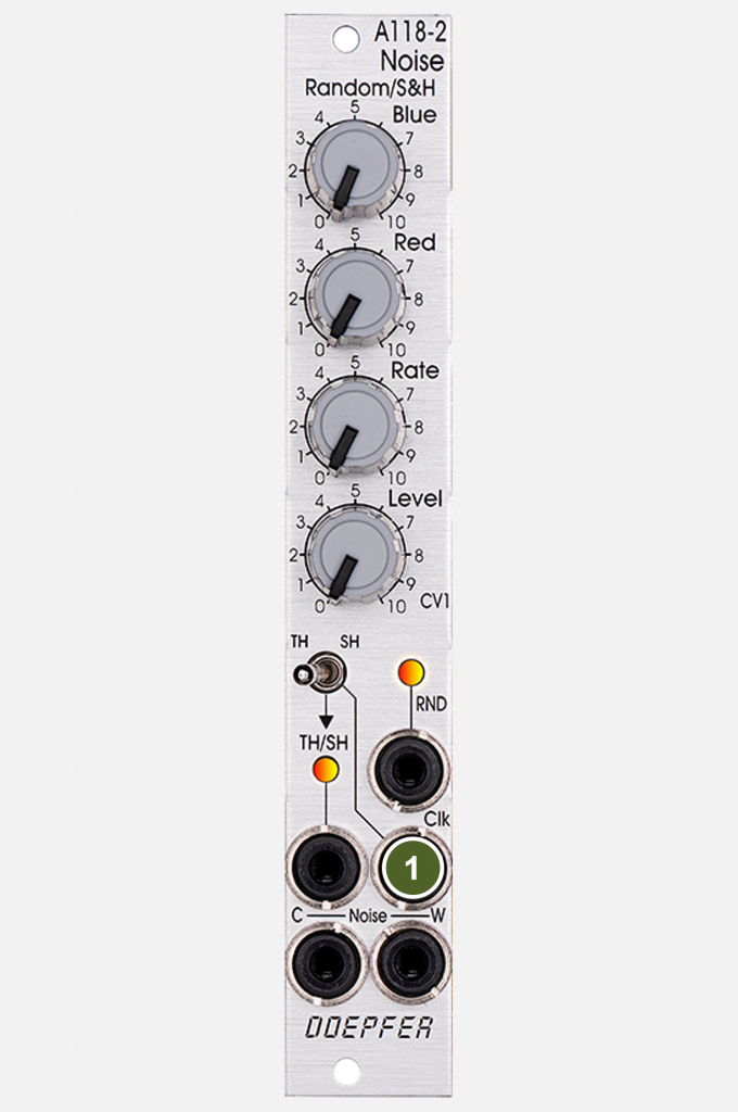
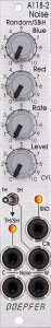
- Clk: Clock input for the Track & Hold / Sample & Hold unit. A gate signal at this input causes the input voltage (in our case the “RND” signal generated by the module itself) to be stored and output at the “TH/SH” output. T&H and S&H differ significantly – details below.
Outputs:
- RND: Output for a continuously changing random voltage. Basically, as with the A-118-1, this is heavily filtered colored noise. The “Blue” and “Red” controls have a significant influence on the characteristics of this random voltage, as do the “Rate” (filter) and “Level” (voltage level) controls.
- TH/SH: Output for the T&H / S&H unit of the module. Here, too, we have a random voltage that can be used for modulation purposes. In contrast to “RND”, however, it is clocked and changes with each gate signal at the “Clk” input.
- Noise C: Colored Noise output. The spectrum is set using the “Blue” and “Red” sliders.
- Noise W: White Noise output. The spectrum is not affected by the module controls.
Controls:
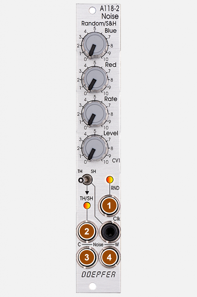
- Blue: Controller for the high-frequency part of the colored noise. This controller influences the spectrum of the colored noise at the “Noise C” output, the random voltage at the “RND” output and the clocked random voltage at the “TH/SH” output.
- Red: Controller for the low-frequency part of the colored noise. This controller also affects the noise at the “Noise C” output and the random voltages at “RND” and “TH/SH”.
- Rate: Low-pass filter (slew limiter) for the random voltage at the “RND” output. Basically, the controller “smoothes” the chaotic colored noise so that at controller position 10 only relatively slow changes in voltage are allowed to pass. At knob position 0 there is less filtering – but there is definitely filtering. The control range is therefore exactly the opposite of that of conventional filters. The range of the filtered frequencies is also significantly lower and extends far below the acoustic threshold of hearing (after all, the primary goal is slow control voltages).
- Level: Control for the level of the random voltage at the “RND” output.
- TH / SH: Switch between Track & Hold or Sample & Hold for the “TH/SH” output.
Sample & Hold vs. Track & Hold
Sample & Hold
The “more well-known” variant first: Sample & Hold uses an input signal, which is often in the audio range, and holds the exact voltage that is present at a control input (here “Clk”) at the time of the rising edge of a trigger/gate signal. This voltage is then output until the next trigger/gate signal holds the then current voltage of the input signal. With a rather high-frequency oscillator signal or – even better – a continuous random voltage as the input signal, as with the A-118-2, we get a clocked random voltage that suddenly changes its value at each gate. And it stays at this value (this constant voltage) until the next gate.
Technically, this is done with the S&H using a capacitor that slowly loses its voltage during prolonged activity. The voltages are not kept “exactly” with any analog S&H that I know of.
Both S&H and T&H are powered by the module’s “RND” signal. This gave us some control over colored noise or just white noise:
- The “Level” control also determines the average level of the S&H / T&H – output signal – down to 0 V at control position 0.
- The input signal is smoothed via the “Rate” control, so that the S&H / T&H output signal levels out to a medium value at high “Rate” settings. At “Rate” = 0, the filtering is the least, but still very clear compared to the original colored noise.
- As with colored noise, the “Blue” and “Red” controls affect the high and low portions of the S&H / T&H output signal.
Track & Hold
T&H is a somewhat “strange” circuit: as long as the gate signal for control is active, the input signal is passed through 1:1. With the A-118-2 this is the self-generated “RND” signal. Only when the gate signal breaks off (falling edge), the last applied voltage (from the “RND” of the A-118-2) is retained, as we know it from the S&H after the rising edge of the gate.
This circuit is rarely found in “classic” synthesizers, the most prominent example being the Korg MS-20. It actually doesn’t have a sample & hold, but a track & hold built in, even if it says otherwise on the front panel. MS-20 users have a little trick to ensure that the T&H still behaves like an S&H: The pulse width of the MS-20’s LFO (“modulation generator”) can be regulated manually. If this pulse width is set to the minimum, there is no 1:1 pass-through of the input signal and the immediately following falling edge from the LFO provides the next constant random voltage.
And of course, with the pulse width of these gate signals, any intermediate states with shorter or longer periods of “permeability” for the input signal can be generated, each interrupted by constant – random – voltages.
A-100 – Users have the A-146 Variable Waveform LFO for such cases, which with its variable pulse width is a pretty handy partner for T&H modules.
The extremely flexible solution of using the “RND” signal as an input for the T&H has a small disadvantage: Even with the lowest possible smoothing of the original noise (i.e. “Rate” = 0) we already have a very heavily filtered colored noise in front of us. This is already much more of a “classic” modulation signal than an audio signal. Personally, I like this wafting random voltage very much, because it can be used as a modulation signal much more discreetly compared to the noise, which often seems a bit strained, but that is – like so many things – ultimately a matter of taste.
Alternatives
A-118-1 Noise / Random Voltage
Sure, the direct predecessor is the most obvious alternative. With 8 TE, the A-118-1 takes up twice as much rack space, but this also means that the buttons that are further apart are also more comfortable to use. The module is also a few euros cheaper.
However, the S&H/T&H unit is missing, so that an additional module is required if clocked random voltages are required, which further increases the space requirement and clearly negates the cost advantage.
The “RND” or “Random Output” signals of the two modules differ (at least with my A-118-1 and A-118-2) in the way the “Blue” and “Red” – Regulators affect this random voltage. Both need a certain proportion of “Red” to generate any major differences in the generated random voltages. With the A-118-1, however, it seems to me to be a bit more symmetrical between positive and negative voltages, while the A-118-2 is only able to generate negative “RND” voltages once “Red” is involved, not before. The influence of “Blue” is much lower on both modules, but on the A-118-2 it reaches a kind of clipping limit from control position 8, after which almost only constant (positive) “RND” voltages are output. This is not the case with the A-118-1. So the new module is a bit more “diva” at this point, which isn’t a bad idea for live performances.
Incidentally, Doepfer points out for both the A-118-1 and the A-118-2 that, for technical reasons, the generation of the noise and the random voltages can take a few minutes. But any analog modular system will be allowed to warm up for more than a few minutes anyway before you can, for example, use analog oscillators with stable tuning.
A-117 Digital Noise / Random Clock / 808 Sound Source
The A-117 is another classic noise generator, but it sounds very different. The noise is generated via random pulses and not from the noise floor of transistors like in the A-118 modules.
Other S&H / T&H modules
An important innovation in the A-118-2 compared to its predecessor is the integrated S&H / T&H circuit. This means that a very large bandwidth of random signals can be generated in a minimal space. Anyone who already owns an A-118-1 could supplement it with an A-148 Dual S&H / T&H instead. It also only requires 4TE and even offers two S&H / T&H circuits, which can also be supplied by any input signals. The A-118-2 is always powered by the internal “RND” signal.
The A-184-1 Ring Modulator / S&H/T&H / Slew Limiter is another such alternative: It also only requires 4TE, allows any input signals for its (individual) S&H / T&H and also offers a ring modulator and a slew limiter to smooth the control voltages generated by S&H / T&H. Here the smoothing takes place afterwards, the A-118-2 already receives a smoothed noise as input material.
If you now think that one or two T&H circuits are children’s stuff, you might want to take a closer look at the A-152 Voltage Addressed Track&Hold / Switch. Here we have a total of eight Track & Hold circuits. All share a common input, but that’s not a disadvantage when generating random voltages with noise or a fast oscillator. However, the previously described trick of turning a T&H into an S&H with very narrow gate signals does not work with the A-152. The corresponding output passes the input signal (e.g. noise) through 1:1 until the next T&H is switched on.
Sound examples
-
A-118-1, A-118-2 / Comparison of white and colored noise
Since the Slim Line Module A-118-2 can basically do everything that is possible with the A-118-1 and also has an S&H / T&H with half the rack space for a small additional charge, direct comparisons are interesting. With all of this, you should of course be aware that analog noise from transistors always involves a certain amount of scatter due to the components: Differences demonstrated here can be caused by different circuits (i.e. they can be REAL differences), but also simply because each A-118-x sounds slightly different than another A-118-x.
In the following we always have the A-118-1 on the left and the A-118-2 on the right. I try to keep the relevant knob positions the same as possible.
White noise: Yes, there are differences, the old A-118-1 (left) seems to have a little more low-frequency components than the new A-118-2 (right).
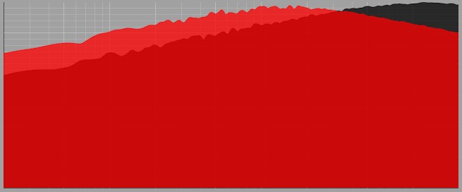
White Noise: Red = A-118-1, Black = A-118-2. White Noise. Left A-118-1, right A-118-2. Colored Noise: Here I try to regulate the blue noise (high-frequency components) from 0 to maximum for both noise generators at about the same time, back to 0, then the red noise also from 0 to maximum and back and finally both blue and red noise from 0 to maximum and back again. I beg your pardon here, as I probably didn’t move the controls completely in sync. In any case, the differences in sound are limited.
As with white noise, my A-118-1 seems to have a slight preference for lows over highs compared to my A-118-2, and to have slightly fewer high-frequency components.
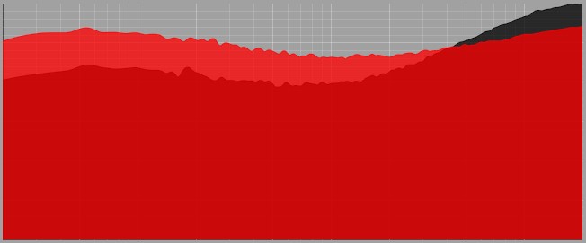
Colored noise (“Blue” and “Red” set to 10): Left A-118-1, right A-118-2. Colored noise: left A-118-1, right A-118-2. Overall, the two modules react very similarly. The differences can be caused by component tolerances, but also by fine-tuning the modules or small adjustments to the circuit design. In practice, however, both modules can be used in the same way.
-
A-118-2, A-111-6 / Sample & Hold, Track & Hold
The A-118-2 controls the filter of an A-111-6 mini synthesizer. The S&H / T&H – clocking, as well as the envelope of the mini synthesizer are triggered together by an A-146 Variable Waveform LFO. Some reverb and delay from the DAW.
Sample & Hold
First we start with “Blue”, “Red”, “Rate” and “Level” at 0, then first the “Level” knob is increased to 10. After that (from about 0:30) the “Red” controller comes into play and creates significantly more dynamics in the generated S&H values (clearly negative voltages). The then also increased “Blue” controller does not change too much. “Blue” values above 8 seem to lead to a kind of internal clipping, so that only relatively constant S&H values are output. Then further manual changes to the color controls, “Level” and “Rate”, in the end everything back to 0.
Sample & Hold. Track & Hold
Same setup as before, this time the A-118-2 is set to “T&H”. Again, all sliders to 0, I start with the “Level” slider and then increase (from 0:20) the “Red” slider. In contrast to the previous sound example, I now change the pulse width of the clock LFOs until it is minimally wide at around 1:00 and the T&H reacts like an S&H. The pulse width is then increased to the maximum so that we have the “RND” signal as the modulation source throughout (approx. 1:30). Then back to medium pulse width and further manual changes, analogous to the S&H example.
Track & Hold.
Technical specifications
| Width | 4 HP |
| Depth | 40 mm |
| Power requirements | 20 mA (+12V) / -20 mA (-12V) |