Like its predecessor A-121, the A-121-2 filter is a multimode filter with 12dB slope that offers separate outputs for highpass, lowpass, bandpass and notch (bandstop). Technically, the filter is a direct offshoot of the “Dark Energy II” synthesizer, which basically uses the same circuitry.
How does it sound? Fine, round, pleasant and in terms of sound it hardly has anything in common with its rather rough predecessor, the A-121. Here too, the resonance can be increased to the point of self-oscillation, which then produces a sine signal. In contrast to the “Dark Energy II” and “Dark Energy III”, which use a technically identical filter, there is a voltage control for the resonance. In addition, the input gain has been increased compared to the A-121, so that significant distortion is now possible even with moderate input levels.
User interface
Inputs:
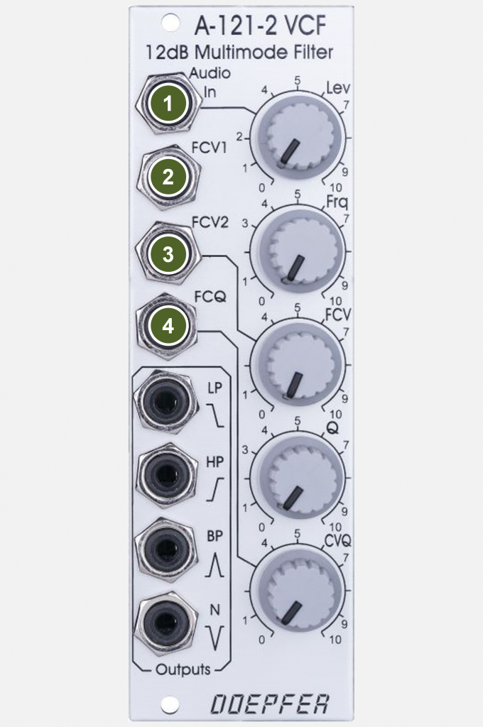
- Audio In: Audio input.
- FCV1: Control voltage input for the cutoff-frequency (without attenuator).
- FCV2: Control voltage input for the corner frequency (with attenuator “FCV”).
- FCQ: Control voltage input for the resonance of the filter (with attenuator “CVQ”).
Outputs:
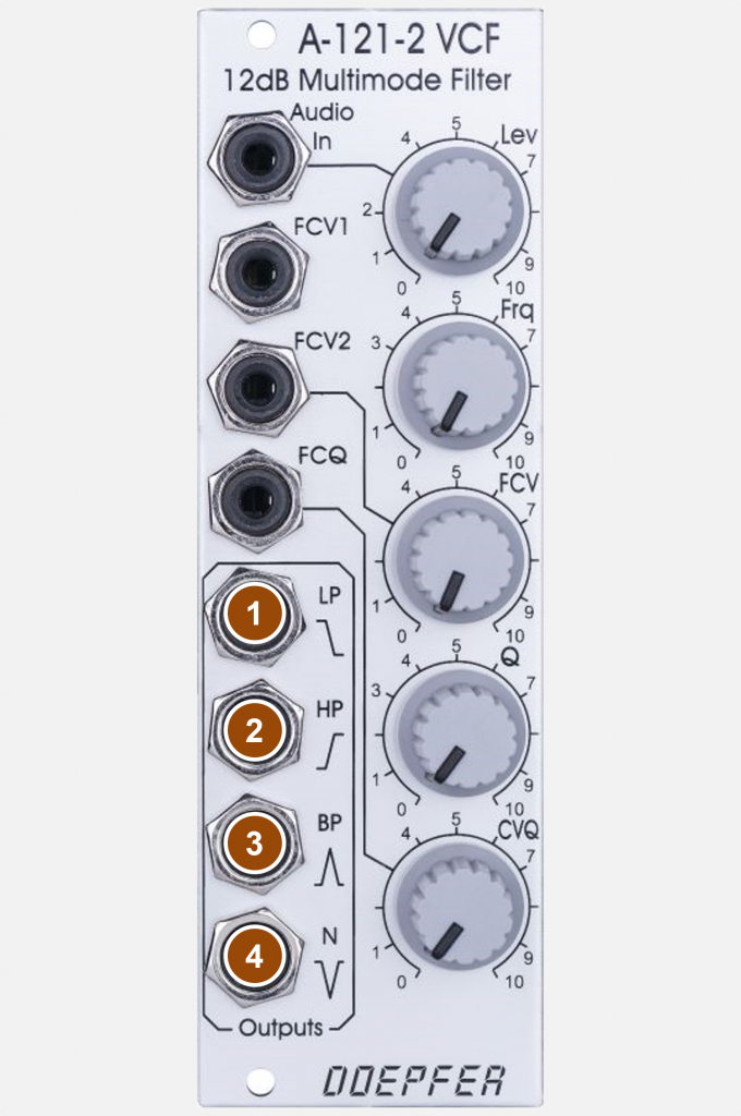
- LP: Audio output for lowpass filter mode.
- HP: Audio output for highpass filter mode.
- BP: Audio output for bandpass filter mode.
- N: Audio output for notch filter (bandstop) mode.
Controls:
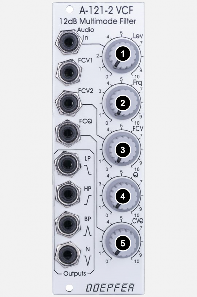
- Lev: Attenuator for the audio input.
- Frq: Controller for the cutoff-frequency of all four filter modes.
- FCV: Attenuator for the control voltage input “FCV2”.
- Q: Filter resonance controller.
- QCV: Attenuator for the control voltage input “FCQ” (to control resonance).
Possible uses
The filter basically has a very comparable range of applications to its predecessor A-121 (see there). In contrast to this, however, it has a somewhat rounder and “nicer” sound, but is equipped with greater scope for overdriving the input signals.
Sound examples
-
A-121, A-121-2 / Comparison of the filters
In the following sound examples I would like to compare the A-121-2 directly with its predecessor, the A-121. Both filters are fed by 3 A-110-1 VCOs (sawtooth outputs, one VCO is transposed 1 octave down). An A-155 sequencer controls the VCOs and two A-140 ADSR generators, which control the filter and the downstream A-132-3 VCA.
With each pass, I start with the maximum filter cutoff frequency, which I manually turn to “0” and then back to the maximum. All settings are the same, due to the significantly higher input gain of the A-121-2, the recording level is slightly reduced there to avoid clipping.
For each filter mode there is a pass with resonance (or “Q”) at 0, at 5 and at 10. The input level is in the middle position at 5. On a fourth run, the input level is at 10 (thus causing distortion of the input signal), the resonance/Q is at 5.
Notch filter:
A-121: Resonance = 0. A-121-2: Resonance =0. A-121: Resonance = 5. A-121-2: Resonance = 5. A-121: Resonance = 10. A-121-2: Resonance = 10. A-121: Input Level = 10 (Res. 5). A-121-2: Input Level = 10 (Res. 5). Highpass filter:
A-121: Resonance = 0. A-121-2: Resonance = 0. A-121: Resonance = 5. A-121-2: Resonance = 5. A-121: Resonance = 10. A-121-2: Resonance = 10. A-121: Input Level = 10 (Res. 5) A-121-2: Input Level = 10 (Res. 5). Bandpass filter:
A-121: Resonance = 0. A-121-2: Resonance = 0. A-121: Resonance = 5. A-121-2: Resonance = 5. A-121: Resonance = 10. A-121-2: Resonance = 10. A-121: Input Level = 10 (Res. 5) A-121-2: Input Level = 10 (Res. 5). Lowpass filter:
A-121: Resonance = 0. A-121-2: Resonance = 0. A-121: Resonance = 5. A-121-2: Resonance = 5. A-121: Resonance = 10. A-121-2: Resonance = 10. A-121: Input Level = 10 (Res. 5) A-121-2: Input Level = 10 (Res. 5)
Technical specifications
| Width | 8 HP |
| Depth | 50 mm |
| Power requirements | 40 mA (+12V) / -40 mA (-12V) |