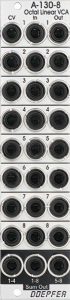
It’s hard to imagine even more VCAs in a small space than the A-130-8 allows. No fewer than eight independent, linear VCAs are housed here in just 6HP. And because there was still some space on the front panel, there are also sum outputs for inputs 1-4, 5-8 or for all inputs 1-8 together. So we also have one or even two voltage-controlled mixers on board. The module can amplify both audio signals and control voltages. As with almost all VCAs, the maximum gain is 1.
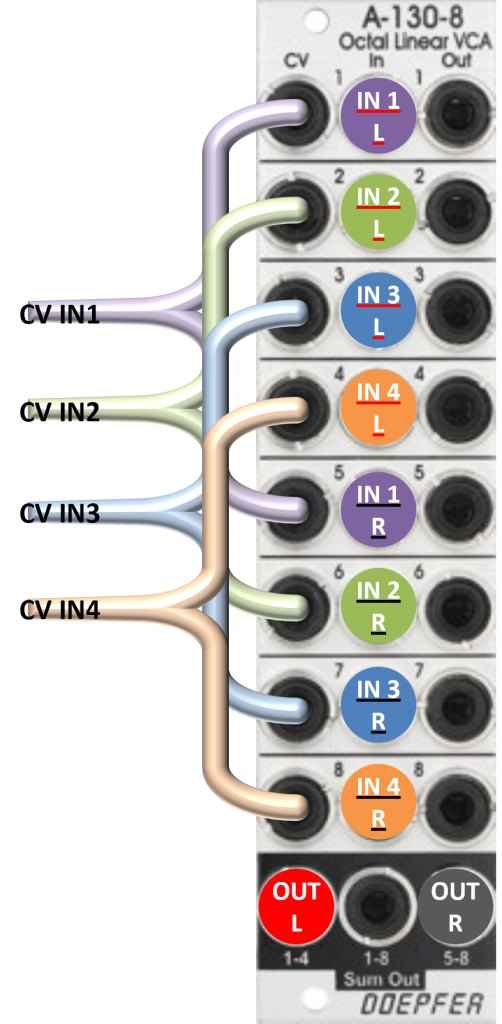
What do you notice? Yes, there is not a single button or switch on the front panel. The input signals and control voltages should be “suitable” beforehand, or you can use a multiple attenuator such as the A-183-5 Quad Attenuator. However, there is no need to worry about the input signals that need to be amplified: the module can handle levels of up to +/- 10V without distorting. Higher voltages are rarely found in Eurorack modules. The sensitivity of the CV inputs can be adjusted internally.
User interface
Inputs:
- CV 1-8: Control voltage inputs for each of the 8 VCAs.
- In 1-8: Inputs for the audio signals or control voltages to be amplified in the 8 VCAs.
Outputs:
- Out 1-8: Outputs for the audio signals or control voltages amplified in the 8 VCAs.
- Sum Out 1-4: Sum output (mixer output) for the audio signals or control voltages from amplifiers 1 to 4.
- Sum Out 1-8: Sum output for all 8 VCAs.
- Sum Out 5-8: Sum output for VCAs 5 to 8.
Possible uses
Eight VCAs, what else?
Wherever you need additional VCAs, for example to specifically process modulation voltages or individual audio signals, the VCAs in the A-130-8 can be easily used. With most modular systems, you are already “settled” with just one of these modules, even if you tend to make very complex patches. The signal processing is very clean, noise or distortion is practically non-existent.
However, there is a limitation if you do not want to control the VCAs with LFOs or manual control voltages (e.g. from joysticks, etc.), but rather use envelopes: The factory setting of the A-130-8 only provides a maximum of around +5V for the “CV” inputs. The venerable A-140 ADSR generator already outputs up to +8V, the newer envelope generators such as the A-140-2 or the polyphonic A-141-4 even go to +10V at the end of the attack phase.
What happens if this value is exceeded?
Actually not much at all. The VCAs remain very well behaved and simply do not amplify any further above their maximum value. There is no distortion or even clipping of the audio signals. Of course, the same applies to amplified control voltages. The behavior is similar to the A-132-3 Dual linear/exponential VCA, which I highly value, in its original version and in its current version with the CEM3360 or AS3360 (the interim version with the SSM2164 distorts if the control voltage is too high).
However, this gain limit does have one disadvantage: the envelopes have a slightly different effect than you would expect. The effect is like a hard clipping of the control voltage (not the audio signal) at the “CV” input:
- ADSR envelopes have a “plateau” between the attack and decay phases, so the attack and decay appear shortened.
- The sustain phase is too high compared to the maximum (at the end of the attack phase), so we lose dynamics.
Overall, as the CV limits are increasingly exceeded, the level curve approaches that of an AHDSR (Attack-Hold-Decay-Sustain-Release) and finally an attack-release envelope, very similar to what a simple audio compressor would do.
If you are not specifically looking for this effect, you can remedy the situation using trim potentiometers on the board and adjust the CV inputs for higher voltages (see section “Configuration via the board”).
Two four-channel mixers or one eight-channel mixer (both voltage controlled)
The module can be used as two independent voltage-controlled four-channel mixers via the “Sum Out 1-4” and “Sum Out 5-8” outputs, and even as an eight-channel mixer via the “Sum Out 1-8” output.
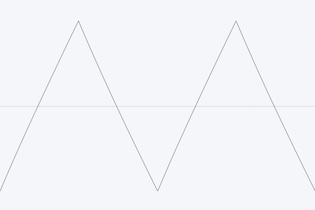
The individual outputs remain unused; the mixes come from the “Sum Out” outputs. For example, in order to create a constantly changing and almost unpredictable mix of four audio signals, the audio sources are connected to the first four “In” sockets. The first four “CV” inputs are connected to the triangle outputs of an A-143-3 or A-145-4 Quad LFO.
If you still have one of the (no longer manufactured) A-144 Morphing Controllers, you can use it to create manual or voltage-controlled morphing. The four outputs of the morphing controller are the control voltages for four “CV” inputs in the A-130-8.
Something similar is possible with an A-143-9 VC Quadrature LFO. However, you have to add a constant offset voltage to the phase-shifted sine signals from the quadrature LFO: As with any conventional VCA, there is no gain in the negative control voltages (the negative oscillation part of the sine). In contrast to the triangle signals of the A-144, the sine control voltages do not produce a completely constant volume with the linear VCAs in the A-130-8.
Stereo Mixer
Similar to the mono mixers described above, you can of course mix stereo signals. If you leave the topic of “panning” aside, then you wire four stereo audio signals as follows:
| Signal: | Input: |
|---|---|
| Audio 1 left | In 1 |
| Audio 2 left | In 2 |
| Audio 3 left | In 3 |
| Audio 4 left | In 4 |
| Audio 1 right | In 5 |
| Audio 2 right | In 6 |
| Audio 3 right | In 7 |
| Audio 4 right | In 8 |
| Control voltage for audio 1 | CV 1 & CV 5* |
| Control voltage for audio 2 | CV 2 & CV 6 |
| Control voltage for audio 3 | CV 3 & CV 7 |
| Control voltage for audio 4 | CV 4 & CV 8 |
All signals for the left channel go to inputs 1-4, those for the right channel go to inputs 5-8, of course in the same order for left and right. The two outputs “Out 1-4” (left channel) and “Out 5-8” (right channel) then serve as stereo outputs. If you need a “mono mix”, you can of course use the “Sum Out 1-8” output.
If you need such a setup permanently, you can pre-wire the CV inputs on the board with a little bit of soldering (see section “Configuration on the board”).
Polyphonic mixer
We actually need two A-130-8s for this! The four outputs “Out 1-4” and “Out 5-8” of both modules then contain the mixes of the audio signals for the four voices of a polyphonic A-100 setup. Alternatively, you can of course also mix control voltages for more complex modulations of the four voices. The principle – and also the control – is exactly the same as with the stereo mix before, except that now two A-130-8s are used for the four required channels.
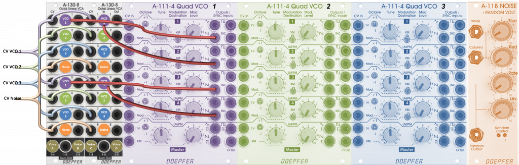
Let’s assume we want to mix three A-111-4s (each sawtooth, but the A-111-4s are transposed differently) and the noise from an A-118-1, to further process the four sum signals in an A-105-4. For every voive, we use one VCO from each of the the A-111-4 VCOs and the noise signal for all voices.
Wiring first voice
The first (top) sawtooth outputs of the three A-111-4 are successively connected to the inputs “In 1” to “In 3” of the first A-130-8, the “White” output with the input “In 4” of the first A-130-8. Between the A-118-1 and the VCA we use a four-fold multiple (e.g. an A-182-1) We need the same signal for the other voices.
Wiring second voice
Now we continue with the second sawtooth outputs of the three A-111-4, they are needed for the second voice. In the same order as with the first voice, we connect it to the inputs “In 5” to “In 7” of the first A-130-8 and the noise signal from the multiple to the input “In 8”.
Wiring third and fourth voices
We continue with the third and then the fourth sawtooth outputs of the VCOs. The third outputs are always connected in the original order to the inputs “In 1” to “In 3” and the fourth outputs to “In 5” to “in 7” of the second A-130-8. This second VCA gets the noise from the multiples twice more: into the inputs “In 4” and “In 8”.
This means that each voice has the outputs from three different A-111-4s and the common noise.
Controlling the mixture
We need four adjustable voltage sources to adjust the ratio between the three A-111-4s and the noise signal. To do this, we use an A-183-5 quad attenuator, which we either supply with a constant voltage in all four inputs or solder the modification suggested by Doepfer as an adjustable quadruple voltage source.
We connect the four outputs of the A-183-5 – divided via multiples or stackables:
| CV output A-183-5: | CV inputs A-130-8: | What audio signal is being controlled? |
|---|---|---|
| 1 | First A-130-8: CV 1, CV 5 Second A-130-8: CV 1, CV 5 | Outputs of the first A-111-4 (e.g. transposed 1 octave down) |
| 2 | First A-130-8: CV 2, CV 6 Second A-130-8: CV 2, CV 6 | Exits of the second A-111-4 (e.g. transposed 1 octave up) |
| 3 | First A-130-8: CV 3, CV 7 Second A-130-8: CV 3, CV 7 | Outputs of the third A-111-4 (e.g. it is untransposed) |
| 4 | First A-130-8: CV 4, CV 8 Second A-130-8: CV 4, CV 8 | Noise from the A-118-1 |
This means that the mix of the three poly VCOs and the noise signal is identical for all four voices.
Instead of the constant control voltages from the A-183-5, we can of course also use four LFOs (possibly also mixed with four offset voltages, because negative control voltages do not cause amplification on the VCAs). Or – if you like it really extreme: Four A-141-4 Poly ADSRs for the control, which then enable individual volume progressions for our four sound sources in each voice. The first A-141-4 then supplies “CV 1” and “CV 5” of both A-130-8, etc.
A bit complex and time-consuming? Yes, sure. The just released A-135-5 Poly Mixer can solve many of these problems in a much more elegant, clearer (and more cost-effective) way. On the other hand… if you already have two A-130-8s, you can easily make do with them and our “basic solution” offers four input signals per voice, while the A-135-5 only offers three. There is also unrestricted access to all 16 CV sources, with the Poly Mixer only to 3. The Poly Mixer has one sub-oscillator per voice, which is pretty practical, as we know from the A-111-6. And it can also be cascaded with a second module, giving us a total of 6 inputs per voice.
Control module for the joystick
The new A-174-4 3D joystick offers a “Z-axis” (turning the control stick) in addition to the voltage outputs for the X and Y axes, as well as control voltages according to quadrants.
Configuration via the board
Unlike many new Doepfer modules, we do not find any jumpers on the A-130-8 that could be used to preset a variety of options in detail.
Input sensitivity for control voltages
Instead there are a series of trim potentiometers for the CV inputs. They’re pretty useful, but of course not quite as trivial to use as inserting or removing a jumper.
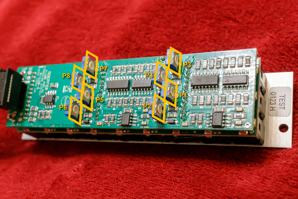
Assigning the trim pots to the inputs is very simple: P1 is responsible for the input “CV 1”, P2 for “CV 2”, etc. If you turn the potentiometers counterclockwise, the sensitivity is increased. If you turn them clockwise, sensitivity is reduced, e.g. to adapt the module to the control voltages of ADSR generators.
To adjust the inputs, an input signal (e.g. an audio signal from a VCO) is patched to the respective “In” input and the maximum control voltage to the matching “CV” input. For ADSRs, sustain is set to maximum (A, D and R to minimum) and a constant gate is applied to the ADSR generator. Now you adjust the trim pot starting with minimum sensitivity (trim pot clockwise all the way to the stop). You turn it counterclockwise until the level of the output signal (at the respective “Out” output) just no longer increases. For “measurement” you can use the level display in the DAW, for example. The result is then the optimal sensitivity for the selected voltage source.
This is then repeated for all VCAs of the module that need to be adjusted. Yes, it takes some work, but it’s hard to go wrong.
Pre-assignment of the signal inputs and CV inputs
Everyone can still manage the trim pots, for the pre-assignments you should already know which side you have to touch the soldering iron on…
There are soldering points on board B that can be connected directly with some soldering tin. This allows you to connect “CV 1” with “CV 2”, “CV 2” with “CV 3”, etc., as well as “In 1” with “In 2”, “In 2” with “In 3”, etc. The connected CV inputs are useful if you want to amplify multiple input signals (e.g. 1-4) in the same way, such as with the A-132-2 Quad VCA or its announced successor A-130-4.
However, for use as a stereo mixer or poly mixer, “CV 1” must be connected to “CV 5”, “CV 2” to “CV 6”, etc.: To do this, a cable is soldered between the upper surface of “CV 1 – CV 2” and the lower surface of “CV4 – CV 5”, between the upper surface of “CV 2 – CV 3” and the lower surface of “CV 5 – CV 6” and so on. In order to get to the soldering points, circuit board A must be removed. This also means that the solid connections between the two boards have to be separated and then soldered back together.
If you’ve never done something like this before, you might want to use multiples or stackables instead. It’s a few more cables, but you definitely can’t go wrong.
Alternatives
A-132-8 Octal polyphonic VCA
In addition to the A-130-8, there is only one eight-fold VCA from Doepfer, the A-132-8. However, it is designed completely differently and offers four VCA pairs, each connected in series – hard-wired. Overall, the control options are designed more for polyphonic use; the two manual gain controls, for example, determine a constant gain of four VCAs each. If you can live without the gain controls, you can use the A-130-8 instead, but you have to do without the (optional) exponential amplification of the Poly-VCA.
A-135-3 VC Stereo Mixer
Wait, I lied! There is actually a second eight-fold VCA: the A-135-3 VC Stereo Mixer! However, it is even more “specialist” than the A-132-8 and mixes four “left” and four “right” inputs into two output signals (left and right).Links und rechts). There are no individual outputs like there are on the A-130-8.
A-135-5 Polyphonic Mixer
Brand new, also highly specialized and with even more VCAs (12 pieces) on board is the A-135-5 Polyphonic Mixer. It offers a mix of three input signals for each of the four voices of a polyphonic A-100 system. Compared to the poly mixer with two A-130-8, it has no individual outputs, but with 10 HP it takes up a little less space, is more cost-effective, has one sub-octaver per voice, can be cascaded… Test follows!
A-132-4 Quad Exponential VCA
The A-132-4 Quad Exponential VCA only offers four VCAs on 6TE, but with exponential characteristics.
A-135-1, A-135-2 VC Mixers
The two VC mixers A-135-1 and A-135-2 also only have four linear VCAs, but with attenuators for CV and input signals. As mixers, both of course also offer a mix output (in addition to the four individual outputs). The comfortably spacious A-135-1 also has four manual gain controls for constant amplification.
A-132-1 Dual VCA
The A-132-1 Dual VCA only has two linear VCAs on 4TE and also does without an attenuator, but offers two control voltage inputs per VCA.
Note to self: It’s time for a comparative overview of all VCAs and VC mixers…
Sound examples
-
A-130-8, A-174-4, A-149-4 / Random sequence with joystick control
The new “3D” joystick A-174-4 is a fairly versatile tool for controlling several parameters of a modular system at the same time. When it comes to amplifying audio signals and/or control voltages, the A-130-8 VCA is an ideal companion.
The sound source of our sequence is four A-111-6 miniature synthesizers with slightly different settings. The “Out” outputs of the mini-synths are amplified via four channels of the A-130-8 VCA. The control voltages for this are provided by the “X-OX”, “Y+OY”, “-X+OX” and “-Y+OY” outputs of the joystick, each with a slight offset (controller at approximately 11 o’clock position).
Two VCOs each are controlled in pitch by two A-149-4 random voltage sources (one A-149-4 is quantized to octaves, the second to major chords with sevenths). The triggers for the mini-synths and the two random generators are generated by two tracks of an A-157 trigger sequencer.
The A-130-8 is not only responsible for the volume of the mini-synths, but – via the remaining four channels – also for modulating the filter cutoff-frequencies through the remaining four outputs in the two random generators. This modulation is controlled via the quadrant outputs “Q1” to “Q4” of the A-174-4 joystick (with the quadrant overlap fully turned up).
Finally, the “Z-axis” of the joystick (rotation of the control stick) directly modulates the envelope times (“CVT” inputs) of the mini-synths, two each via the “Z-OZ” and two via the “-Z+OZ” output (no offset). Apart from the joystick, there is no manual intervention in the sequence.
Random sequence controlled by joystick and eight-way VCA. -
A-130-8 / “Shepard Tones” (or something similar)
Shepard tones are a psychoacoustic effect in which a melody, for example, seems to rise endlessly. In the original version, this was achieved with rows of overtones, the mixing ratio of which was shifted relative to one another, so that the fundamental tone was slowly faded out and then the first overtone, etc., only to be faded in again later.
A similar effect can also be achieved by mixing tones whose frequency is modulated in the form of a rising sawtooth signal while the amplitude is modulated in a triangle. If you now use four modulation signals (sawtooths and triangles), each phase-shifted by 90 degrees, a tone with increasing frequency will be faded in and faded out again. When the sawtooth is reset, the amplitude modulation is set so that the jump is not audible. The second tone is modulated in the same way, but – phase-shifted modulation – slightly delayed in time, as are the third and fourth tone. This means that you always hear a mixture of rising tones, which are faded out at the end and then slowly fade in again (at a lower frequency).
There was a very early Doepfer module for such purposes, the A-191 Midi-CV / Shepard Generator, which has been out of production for a long time: It had a total of 8 triangle and sawtooth outputs, each of which was 45 degrees out of phase. The module was far ahead of its time; the idea that you could use eight (!!!) VCOs and the same number of VCAs in a modular system seemed completely absurd at the time. Today we have inexpensive multiple modules with the A-111-4 and the A-130-8, but unfortunately we no longer have a Shepard generator. A module A-144-4 with at least four Shepard LFOs seems to be in the planning stage, let’s see what happens.
The “closest relative” is the A-143-9 VC Quadrature LFO, which outputs four sine signals, each 90 degrees out of phase. Couldn’t we use this one…? Unfortunately not satisfactory: For frequency modulation, we can only use the rising part of the sine curve. What we actually need is a rising sawtooth. And for amplitude modulation, only the positive part of the sine wave works (VCAs normally cannot amplify negatively, so we would need a precise four-fold offset generator). If you use the four sine outputs for frequency modulation and the following one (cosine etc. output) for amplitude modulation, the result is a mixture of VCO signals that always increase in frequency. Due to the “dead times” of the negative sine waves as a VCA modulation source, we only ever get two VCOs that sound at the same time – and we can still “see through” (or “hear through”) this reduced solution.
Long preface for a small sound example, sorry…
I use two A-141-4 poly-ADSR generators as modulation sources for the four oscillators in an A-111-4 VCO for the reasons mentioned previously. I try to set the envelope so that the frequency modulation always increases. The ADSR signals run through an A-138j Janus mixer, which inverts all four envelopes (no attack and sustain, just decay and release). For the A-130-8 I use a second A-141-4 poly-ADSR, which is set roughly like a triangle via attack and decay/release.
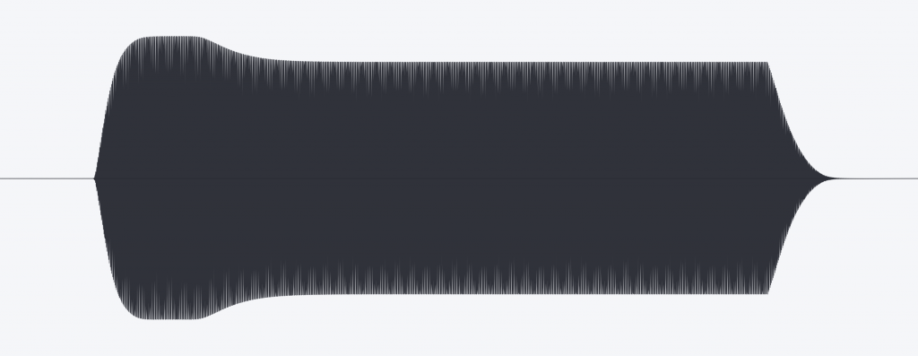
The triggers for the envelopes come from an A-152 Voltage Addressed Switch, which is switched through with an LFO as a trigger and performs a reset at step 5. The envelopes are set so that they overlap each other very generously (over the release times). In the “oscilloscope” (waveform representation of the DAW) it looks like this for the four VCO signals:
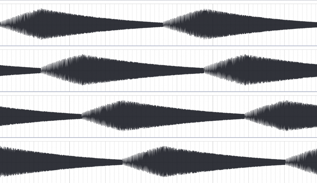
At the beginning of the amplitude you can see the low frequency, which is continuously increased, while the amplitudes decrease again somewhere in the middle. The decay/release time I chose, for example, is clearly too long! This is – admittedly – a pretty “hand-carved” version of a Shepard generator, but the sonic result is already in the right direction. With more time and fine-tuning, the result could probably be optimized:
Very rough “replica” of a Shepard generator. -
A-130-8, A-144 / Audio morphing
We often use morphing in a very “comfortable” way, like a kind of extended crossfading, for example with “vector synthesis,” which was quite popular at the time. We stir multiple audio sources with a joystick (or similar tools like multiple envelopes) and enjoy the tonal change.
But you can also go to the “atomic level” of a sound – the individual vibration forms of an oscillator. And of course you can also crossfade at oscillator speed: A pulse wave starts, is interrupted on the way and replaced by a triangle, which also suffers the same fate long before the end of an entire oscillation cycle: It is replaced by a triangle and then by a sine (or here again a part of a sine oscillation). If you do this with smooth transitions, interesting new waveforms emerge. And if this morphing takes place with an approximately (but not quite!) synchronous beat, then the sound is constantly changing.
The only problem: In addition to a linear multiple VCA/mixer like the A-130-8, you need a morphing generator for it. From a linearly increasing voltage, it generates four individual triangular voltages, each 90 degrees out of phase, which then fade the audio signals in and out via four linear VCAs so that the audio level always remains the same.
The A-144 Morphing Controller was one such module, unfortunately it is no longer in production. An expanded successor A-144-4 has been announced, we are of course very excited to see what it can do!
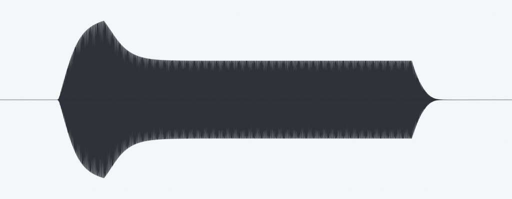
Setup: The pulse (not set symmetrically as a square wave), triangle, sawtooth and sine outputs of an A-111-1 VCO are the input channels 1-4 for the A-130-8. The outputs “Out 1” – “Out4” of the morphing controller control the gain via the first four CV inputs. Inputs 5-8 of the amplifier are also supplied – in reverse order – with the outputs of the VCO; the amplification is analogous to the first four inputs. The mix outputs “Sum Out 1-4” and “Sum Out 5-8” go hard left and right into the DAW. The morphing controller is modulated by a second A-111-1 VCO (triangle output).
I start without modulation and slowly increase the CV modulation of the A-144, then slightly change the frequency of the (previously largely synchronous) modulation VCO and the modulation depth on the morphing controller.
What happens? With absolutely synchronous audio VCO and morphing modulation VCO, an unusual sound is created that arises from the regular “cutting together” of fragments of the various VCO waveforms. If the synchronization slowly drifts apart, slightly different fragments of the original VCO waveforms are strung together in each morph pass – the static sound begins to move.
Morphing at audio speed. -
A-105-4, A-130-8 / Filter FM again
Here I use the sawtooth outputs from the A-111-4 as sound sources, this time the filter FM is handled by the triangle outputs. These are now modulated in amplitude by the envelope signals of the A-141-4 using an A-130-8 Octal Linear VCA before they go into the A-105-4. I tweak the resonance, input level and overall FM of the filters manually. Delay and reverb again from the DAW.
Filter FM again. -
A-111-4, A-130-8 / Detuning of oscillators
Especially with monophonic synthesizer voices, it is often worth slightly detuning the individual VCOs against each other. If you do it discreetly, it doesn’t sound “out of tune” but very broad and “floating”. Now you can of course start playing around with the four “Tune” controls, but if you then want to quickly get back to the original tuning, you still need a good ear and sensitive fingers.
Instead, I use an A-143-9 VC Quadrature LFO set very slowly as the modulation source and four VCAs in an A-130-8 Octal VCA to control this modulation. In addition, a manual voltage source controls this modulation – distributed over the four CV inputs of the A-130-8. The four outputs from the A-130-8 go into the A-111-4‘s four “Mod” inputs, all set to “XM”. The four “Mod. Level” attenuators in the A-111-4 are all set to small values (e.g. 1).
The audio path in this sound example looks like this: The four sawtooth outputs from the A-111-4 (one transposed +1 octave, another -1 octave) go into the A-105-4 filer and then into the A-132-8 VCA. Filter and VCA are controlled by an A-141-4 ADSR.
CV and trigger: The entire sequence is transmitted by the A-190-5 in “unison” mode, Midi source is an Arturia KeyStep37. During the sequence, I slowly turn my “Detune knob” from 0 through very subtle detuning to fairly obvious “out of tune” values and back again.
Detune.
Technical specifications
| Width | 6 HP |
| Depth | 40 mm |
| Power requirements | 50 mA (+12V) / -50 mA (-12V) |