The family of A-111 oscillators now includes an impressive 6 variants, all of which use the Curtis chip CEM3340 (or replica) with its triangular core and allow very precise tracking over 10 octaves and more.
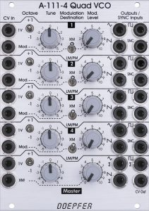
The A-111-4 is – nomen est omen – designed fourfold and also has a common “master” section, which affects all 4 oscillators simultaneously. This makes the module predestined for use in a polyphonic modular system, but by no means limited to it.
User interface
Inputs:
System bus: The A-111-4, which is suitable for polyphonic purposes, has access to the A-100 system bus and its monophonic VCO control voltage, e.g. given to the bus by most midi CV interfaces. Why? There is nothing wrong with using the A-111-4 as a very powerful multiple VCO in monophonic applications. In addition, an A-185-2 Precision Adder / Bus Access installed on the same bus, for example, offers additional options for transposing all 4 oscillators simultaneously, even in polyphonic use.
The control voltage from the system bus is used in the master section of the module, where it affects all four oscillators – together with the control voltages from the “1V” and “XM” inputs and the master octave switch.
As with all VCOs with CV control via the bus, you should deactivate this option if you are not using it: Otherwise, the open lines could work as “antennas” and pick up interference signals.
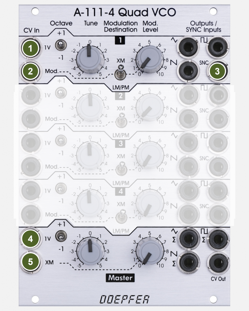
Inputs per oscillator:
- 1V: Control voltage input with 1V/octave characteristics for pitch control by a sequencer, keyboard or the A-190-5 midi interface.
- Mod.: Control voltage input with attenuator that can be used for either exponential frequency modulation “XM”, linear frequency modulation “LM” or pulse width modulation “PM”.
- SNC: Sync input, optionally for soft sync or CEM3340-specific hard sync (jumper selectable).
Inputs in the “Master” section (common for all 4 oscillators):
- 1V: Control voltage input with 1V/octave characteristics for pitch control by a sequencer, keyboard or the A-190-5 midi interface.
- XM: Control voltage input for exponential frequency modulation. The input is equipped with an attenuator.
Outputs:
Outputs per oscillator:
- Triangle: Single audio output for the triangle waveform.
- Sawtooth: Single audio output for the sawtooth waveform.
- Square: Single audio output for the square waveform. Changing the pulse width is only possible with the active “PW” option (switch resp. jumper on the circuit board).
Outputs in the “master” section (sum outputs):
Audio signals that are tapped directly from one of the individual outputs are not included in the respective audio sum output.
- Triangle Sum: Sum output for the triangle waveforms of all 4 oscillators.
- Sawtooth Sum: Sum output for the sawtooth waveforms of all 4 oscillators.
- Square Sum: Sum output for the square waveforms of all 4 oscillators.
- CV Out: Sum of “1V” and “XM” from the master section, the master octave switch and the control voltage from the A-100 bus.
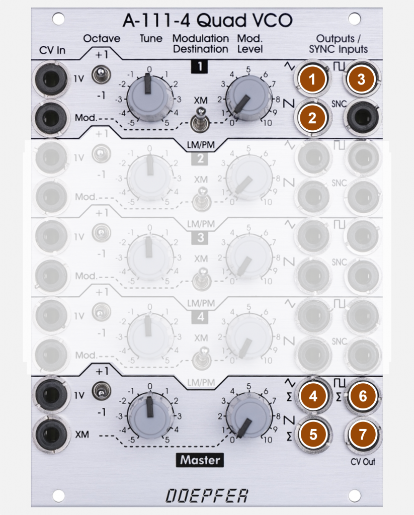
Controls:
Controls per oscillator:
- Octave: Switch to transpose the oscillator one octave up or down (middle position = not transposed).
- Tune: Control for fine-tuning the oscillator.
- Modulation Destination: Switch for the destination of the control voltage at the “Mod.” input. – in position “XM” exponential frequency modulation, in position “LM/PM” either linear FM or pulse width modulation (depending on one jumper per oscillator on the board).
- Mod. Level: Attenuator for the control voltage at the “Mod.” input.
Controls in the “Master” section:
- Octave: Switch to transpose all 4 oscillators one octave up or down (middle position = not transposed).
- Tune: Control for the fine tuning of all four oscillators together.
- Mod. Level: Attenuator for the common control voltage at the “XM” input (exponential frequency modulation of all four oscillators).
Overview
Each of the four oscillators has a “1V” input to play it tonally. If the switch socket is not used, then the default wiring, which can be made on the circuit board, applies. There is also a “Mod” input with an attenuator that can be used for conventional exponential frequency modulation, linear frequency modulation or for pulse width modulation of the square wave.
Each of the four oscillators can output triangle, square (or modulated pulse) and sawtooth, and there is a sync input for each VCO (either soft sync or hard sync). There is a tune control and a three-stage octave switch for each VCO.
There is a common tune control and a common three-stage octave switch for all four VCOs together. There is also a common “1V” input, a common modulation input for exponential FM and (optionally) a common access to the 1V/octave control voltage in the A-100 bus.
For paraphonic/monophonic applications, there are audio sum outputs for triangle, square (or modulated pulse) and sawtooth, as well as a CV sum output for the common control voltages (on which the individual CV inputs per VCO have no influence).
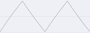
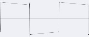
Waveforms
There are no surprises here. As with all CEM3340-based A-111 modules, the waveforms are very precise and without significant distortions.

Setting options via the circuit board
Doepfer has been offering a variety of “customizing” options on the module circuit boards for several years. As a rule, these are settings that rarely need to be changed, for which you then have to briefly remove the module and change the position of jumpers. Due to the complexity of the module, the A-111-4 has a total of 14 jumpers as well as four pins for preassigning the “1V” inputs.

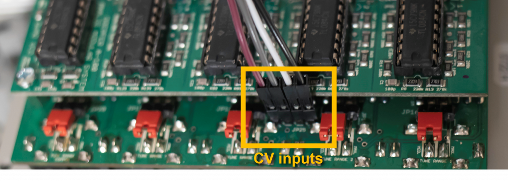
Connection to the CV outputs of the A-190-5
The A-111-4 can be connected directly to the control voltage outputs “CV Note” of the polyphonic A-190-5 interface via jumper wires (so-called “Arduino” or “Raspberry Pi – cables”).
Synchronisation
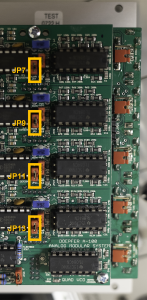
The four oscillators are capable of both conventional soft synchronization and the special “Curtis hardsync”. With the jumpers JP7, JP9, JP11 and JP13 on board A you can set for each oscillator whether it can be synchronized with softsync (jumper in the upper position) or with hardsync (jumper in the lower position).
The jumpers are located immediately to the left of the modulation destination jumpers JP8-JP14 (see the following section).
By the way, to the right of the jumper pairs you can see the four CEM3340 ICs, including board B with additional jumpers and the pins for connecting to the A-190-5 interface.
Modulation: Linear FM or pulse width modulation
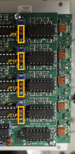
In the lower position of the 4 “Modulation Destination” switches, the control voltage from the “Mod.” inputs is used either for linear frequency modulation or for pulse width modulation. With the jumpers JP8, JP10, JP12 and JP14 on board A one can determine per oscillator whether PWM (jumper in the up position) or linear FM (jumper in the down position) is the target.
The jumpers are located immediately to the right of the JP7-JP13 synchronization jumpers.
Access to the control voltage in the A-100 bus
In addition to all other modulation sources, the bus CV can be used to transpose the four oscillators together. If you don’t want to use the A-111-4 polyphonically, you can also use a conventional Midi-CV interface such as the A-190-3 and use the interface’s bus connection to play the oscillators. If jumper JP15 is set, bus access takes place, without a jumper the bus CV is ignored.
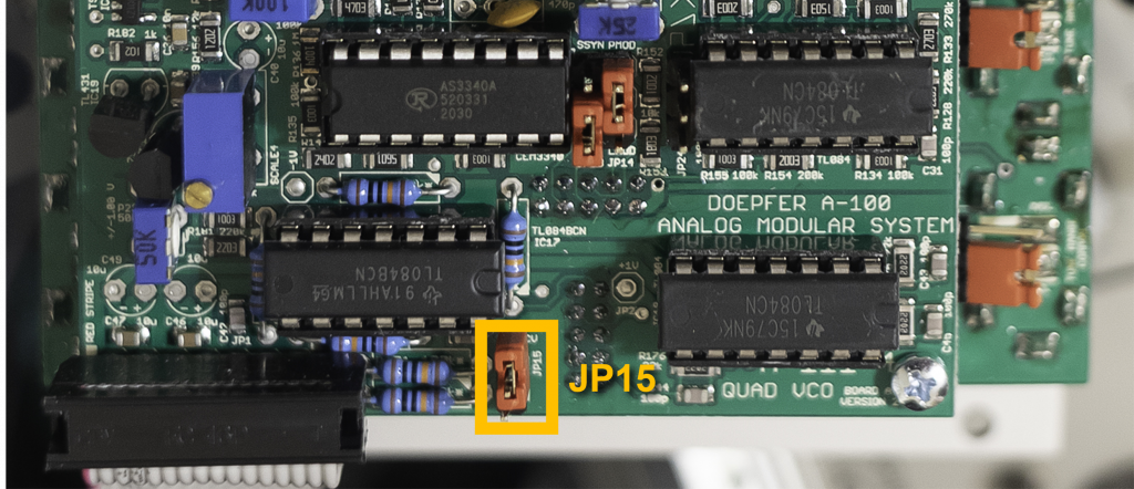
Doepfer points out that this option should only be set if there is actually a voltage source on the bus (e.g. an A-185-2). An “unused” CV bus can otherwise act as an antenna and emit unwanted interference voltages to the VCOs connected to it.
Control range of the “Tune” knobs
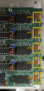
For each of the 5 “Tune” controls, the control range can be set with the jumpers JP16, JP17, JP18, JP19 (oscillators 1-4 individually) and JP20 (master section):
| Jumper position: | Control range: |
|---|---|
| top | approx. 5 octaves |
| bottom | approx. 1 octave |
| without jumper | about 2 semitones |
Softsync and hardsync
The jumpers described above can be used to specify for each VCO whether it is synchronized via “softsync” or “hardsync” with a square-wave signal at the “SNC” inputs.
The exact behavior of softsync and hardsync is quite complex and also depends on the ratio of the frequencies between the sync master and slave. There are also some differences as to whether the rising or falling edge of the sync signal leads to a reset of the synchronized VCO.
This will be examined in detail again in a “Special post” comparing all VCOs. In any case, the hardsync on the Curtis-based A-111-x VCOs reacts somewhat differently than the hardsync on the A-110-x VCOs.
To compare softsync and hardsync on the A-111-4, there is a small audio example below.
Alternatives
With its four VCOs and the possibility of obtaining the control voltages of the VCOs via jumper cables directly on the circuit board (i.e. without patch cords) from a polyphonic A-190-5 Midi-CV interface, the A-111-4 is relatively unrivalled.
The “other” quad VCO: A-143-4
In fact, the A-143-4 was originally designed as a pure quad LFO and not as a VCO. However, it has been given a Tempco unit (that’s a small “heater”) to stabilize the tuning even with changing ambient temperatures, as well as a switch between LFO and VCO mode, so that it can also be used as a quadruple VCO if necessary.
However, there are significant limitations. In contrast to the four clearly separated CEM3340 ICs for the VCOs in the A-111-4, all VCOs in the A-143-4 are housed in a very small space and can mutually synchronize at very similar frequencies (“oscillator lock”). The sync options also have side effects in VCO mode and the 1V/octave control is much less precise. And last but not least: The A-143-4 has no sawtooth outputs and no pulse width modulation.
I like to use the A-143-4 as a sound source for drones, because the oscillators can be brought into mutual dependence and also be switched individually to LFO mode. And even the otherwise little loved “oscillator lock” has its appeal with drones.
In a polyphonic context, the A-143-4 is a great modulation source for pulse width modulation of the A-111-4 oscillators when controlling the speed of the VCLFOs through the A-190-5‘s “CV Note” outputs. Higher tones sound better (to me) with faster PWM, lower tones with slower PWM.
Is the A-111-4 a replacement for multiple A-111-2 VCOs?
The “normal” A-111-2 with its 14 TE is quite a large piece of gear. If you get “four of them” with a single A-111-4, which costs less than half of four individual A-111-2, you start to ponder. So what was saved on the A-111-4?
- Octave switch: The A-111-2 can be transposed over 6 octaves with a small rotary switch, the oscillators in the A-111-4 can be transposed individually over 3 octaves with a toggle switch. Only together with the common octave selector switch in the “Master” section of the A-111-4 are 5 octaves possible, although not independently for all 4 oscillators.
- Modulation: The A-111-2 allows simultaneous linear and exponential frequency modulation as well as pulse width modulation, each with a modulation input and an attenuator. With the A-111-4 we only have a single modulation input and CV attenuator per oscillator. This means that exponential FM, linear FM or PWM can only be used alternatively. In addition, the switch for the type of modulation is unfortunately only designed in two stages, so that you have to use a jumper on the circuit board to choose whether you want to use linear FM or pulse width modulation with the lower switch position.
- Sync: The A-111-2 has dedicated inputs for softsync and the CEM3340 specific hardsync. Both types of synchronization are also available with the A-111-4, but you have to choose which option you want to use using a jumper on the circuit board.
- Waveforms: The A-111-2 has a very precise sine converter and can therefore also output sine waves in addition to sawtooth, square/pulse and triangle, the A-111-4 is limited to sawtooth, square and triangle. Pulse is only possible in connection with switched on pulse width modulation (exponential or linear FM are then deactivated).
These limitations are somewhat compensated for by the master section of the A-111-4, which allows all four oscillators to be transposed +/- 1 octave and modulated exponentially together. In addition, the jumper settings mentioned above can be set separately for each of the four oscillators.
Would you rather have four A-111-3s?
If space is the only issue, four A-111-3, each with 4 HP, are an attractive option: The A-111-3 has separate CV inputs for exponential and linear frequency modulation, as well as for pulse width modulation. The A-111-3 has an attenuator for exponential FM, but not for linear FM and PWM.
However, the other limitations compared to the large A-111-2 also apply to the A-111-3:
- No octave switch on the A-111-3, here the A-111-4 “scores” with 3 octaves (or 5 octaves if you add the switch in the master section).
- The sync variant can also only be switched via jumpers.
- The A-111-3 also has no sine output on board. Here you may have to use an A-184-2 sine wave converter.
- In the context of a polyphonic setup, the A-111-4 has the great advantage that the CV inputs for the pitch of the oscillators can be pre-assigned via pins and jumper cables on the circuit board. Neither the A-111-2 nor the A-111-3 offer that.
Sound examples
-
A-111-3, A-111-4, A-150-8 / Polyphonic VCO-Switching
In this patch I use four A-111-3 VCOs as an alternative to the four VCOs in an A-111-4 poly VCO. The audio signals (each sawtooth) are switched per voice between A-111-3 and A-111-4 by an A-150-8 octal VC switch and then filtered in an A-105-4 quad poly VCF.
The voices are played manually on a midi keyboard, which controls the VCOs via a polyphonic A-190-5 midi interface and triggers the two A-141-4 quad polyphonic ADSRs. Der erste Poly-ADSR steuert das A-105-4 Filter, der zweite einen A-132-8 Octal Polyphonic VCA.
The switching operations in the A-150-8 switch are controlled by the square-wave outputs of an A-143-4 Quad VCLFO/VCO, the LFO speeds are also controlled per voice from the “CV Note” outputs of the A-190-5 interface (roughly approx. 1V/octave). Each keystroke resets the corresponding LFO so that the switching processes start in sync with the notes.
Some reverb and delay from the DAW. Otherwise, I just doodle on the keyboard.
You can hear the volume differences between the A-111-4 (5 Vpp) and the A-111-3 VCOs (10 Vpp) very clearly, which also saturate the filters to different degrees.
Four A-111-3 VCOs are used alternately with the VCOs of an A-111-4, controlled by four LFOs. You could of course use four VCAs instead, which achieve a similar effect with different volumes, but it is something different when two different VCOs do the job, which (despite hopefully reasonably careful tuning) then have very small differences in pitch, but also in the sound spectrum.
-
A-111-3, A-111-4, A-149-5 / Polyphonic sequence with linear FM
Four A-111-3 VCOs (triangle outputs) are used as modulation sources for frequency modulation (linear) of the four VCOs in an A-111-4 (sawtooth outputs). All VCOs are controlled by an A-190-5 Poly Midi interface, so the modulators are (roughly) the same pitch as the modulated VCOs.
The sawtooth signals are filtered by an A-105-4 poly VCF and then amplified in an A-132-8 poly VCA. Filter and VCA are each controlled by an A-141-4 Poly ADSR. The A-111-3 VCOs cannot be heard directly and are only a modulation source.
The amount of frequency modulation is controlled using four channels in an A-130-8 via the velocities (also from the A-190-5). The little polyphonic sequence is from an Arturia KeyStep Pro.
In addition, one channel of an A-149-4 transposes the four A-111-4 VCOs simultaneously via the shared 1V input. The Random Generator is triggered by the first voice of the A-190-5. The A-111-3 VCOs are not transposed.
I start without random transposition, then increase the “Range” value in the A-149-4, first only with octaves, later also with fifths and chords, finally with the major scale and back again. At the very end the frequency modulation is withdrawn and the filter is slowly closed.
Linear FM with four A-111-3 and one A-111-4. -
A-111-4, A-130-8 / Detuning of oscillators
Especially with monophonic synthesizer voices, it is often worth slightly detuning the individual VCOs against each other. If you do it discreetly, it doesn’t sound “out of tune” but very broad and “floating”. Now you can of course start playing around with the four “Tune” controls, but if you then want to quickly get back to the original tuning, you still need a good ear and sensitive fingers.
Instead, I use an A-143-9 VC Quadrature LFO set very slowly as the modulation source and four VCAs in an A-130-8 Octal VCA to control this modulation. In addition, a manual voltage source controls this modulation – distributed over the four CV inputs of the A-130-8. The four outputs from the A-130-8 go into the A-111-4‘s four “Mod” inputs, all set to “XM”. The four “Mod. Level” attenuators in the A-111-4 are all set to small values (e.g. 1).
The audio path in this sound example looks like this: The four sawtooth outputs from the A-111-4 (one transposed +1 octave, another -1 octave) go into the A-105-4 filer and then into the A-132-8 VCA. Filter and VCA are controlled by an A-141-4 ADSR.
CV and trigger: The entire sequence is transmitted by the A-190-5 in “unison” mode, Midi source is an Arturia KeyStep37. During the sequence, I slowly turn my “Detune knob” from 0 through very subtle detuning to fairly obvious “out of tune” values and back again.
Detune. -
A-111-4 / Mono synth with hardsync
Although the oscillator is predestined for polyphony, you can also use it monophonically (or “unisono”) very nicely. The A-190-5 is therefore set to “unisono”, i.e. it outputs all incoming midi notes simultaneously on all 4 voices.
I only use the triangle waves from the first and third oscillators of the A-111-4 as a sound source. VCOs 2 and 4 are not audible, but control the sync inputs of VCO 1 and 3 with their square waves, both are set to hard sync.
In addition, VCO 1 and 3 are modulated exponentially in frequency by the envelopes of the A-141-4 and are set to different pitches or octaves. The audio path goes from the VCOs into the A-105-4 and then into the A-132-8, both also controlled by the A-141-4 envelopes. Finally, the two output signals are distributed in the stereo image.
Hardsync. -
A-111-4 / Linear FM
The two A-111-4 oscillators 1 and 2 work as “carriers”, i.e. they are modulated and then filtered. The other two VCOs, Nos. 3 and 4, are the modulation sources and are therefore not patched into the audio path. In order for the frequency modulation to be dynamic, I use the A-132-8 on the first two channels as a normal audio VCA for the two filtered VCOs 1 and 2, but on channels 3 and 4 as a modulation amplifier for the other two VCOs.
Different envelopes for audio and FM make sense for this application, so two A-140-2 are used
Linear frequency modulation (and softsync). -
A-111-4 / Softsync vs hardsync
Two of the four oscillators from the A-111-4 are used as a sound source. No filters, VCAs, echo or reverb.
VCO1 with its triangle output is on the far left in the stereo image and is synchronized via hardsync, VCO2 analogously with its triangle on the far right and is synchronized via softsync. The pitch of these two VCOs is modulated very slowly (“1V” inputs) with the 180 degree phase-shifted sine outputs from an A-143-9.
The square (pulse) outputs of the two remaining VCOs are used as sync masters, which are otherwise not directly audible in the sound example. The frequency of both VCOs is fixed, the pulse width is modulated by another (faster) A-143-9.
So we hear hardsync on the left and softsync on the right, the modulation of the slave VCOs starts first on the left and then on the right due to the phase shift.
What do you notice? The modulation via hardsync (left) creates something like side tones / harmonics that change during the modulation of the slave VCO. With soft sync (right), these secondary tones are not as clear, but the result is a bit “scratchy”, so there are completely different artefacts than with hard sync.
Hardsync on the left, softsync on the right. -
A-111-4 / Polyphonic with four A-108s
This time, the sawtooth outputs of the A-111-4 are processed by four A-108 ladder filters, the 12dB outputs of the filters go into the A-132-8 VCA. Personally, I like the A-108 very much, they have an inimitable “smacking” sound, which I think goes very well with polyphonic sequences, especially in 12dB mode (that’s of course a very personal view of things…)
Modulations: The A-141-4 ADSR controls VCAs and filters, velocity from the A-190-5 controls the VCAs, pitch CV from the A-190-5 controls the filters. In addition, an A-110-6 modulates the filter frequency, as well as decay and release in the A-141-4 ADSR.
Four A-108 as filters in polyphonic setup -
A-111-4 / Polyphony with pulse width modulation
From the A-111-4 I use the square outputs, pulse width modulated by the four VCLFOs in the A-143-4. Due to the beats of the pulse width modulation, you can already create very full and round sounding sequences with a single A-111-4. The frequencies of the LFOs are also modulated by the “CV Note” outputs of the A-190-5 interface, so the modulation on lower notes is slower than on higher notes. The interface is in “poly” mode.
The audio signals pass through the polyphonic A-105-4 filter and the polyphonic A-132-8 VCA. Filters and VCAs are controlled by the A-141-4 ADSR.
With its phase-shifted sine waves, an A-143-9 quadrature LFO modulates the filter FM and resonance of the A-105-4 as well as the attack and decay times of the A-141-4. Some reverb and delay from the DAW.
Pulse width modulation.
Technical specifications
| Width | 18 HP |
| Depth | 40 mm |
| Power requirements | 120 mA (+12V) / -100 mA (-12V) |