The A-105-4 is a polyphonic filter module based on the SSM2024 integrated circuit (or its replica SSI2144). In principle, we have four A-105 filters with a common control in front of us: Cutoff frequency, resonance (called “Q” here) and input level can be set in the same way for all four filters or also controlled together via control voltages.
In addition, each of the 4 filters has an individual modulation input for the cut-off frequency. The modulation intensity of these 4 voltage sources can be adjusted together via the “FM” controller or – and the original A-105 could not do this without an additional VCA – influenced via an additional control voltage in the “CVFM” input.
In order to realize this, Doepfer obviously installed a whole lot of VCAs in the module. Polyphony in the modular system is a demanding subject: What is otherwise done by a simple potentiometer must run through several parallel amplifiers with polyphony, which also work over comparable ranges (adjustment effort!), so that all “voices” can be controlled in the same way. This is a small “marvel” on only 8 HP.
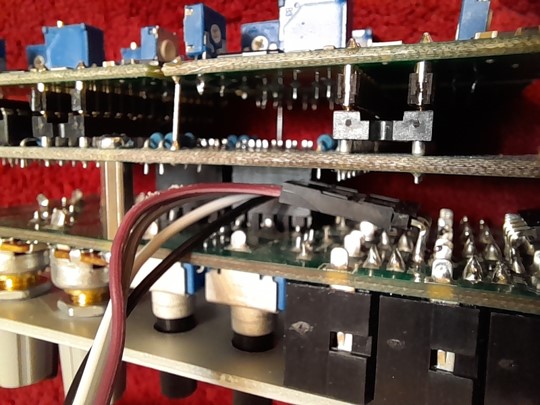
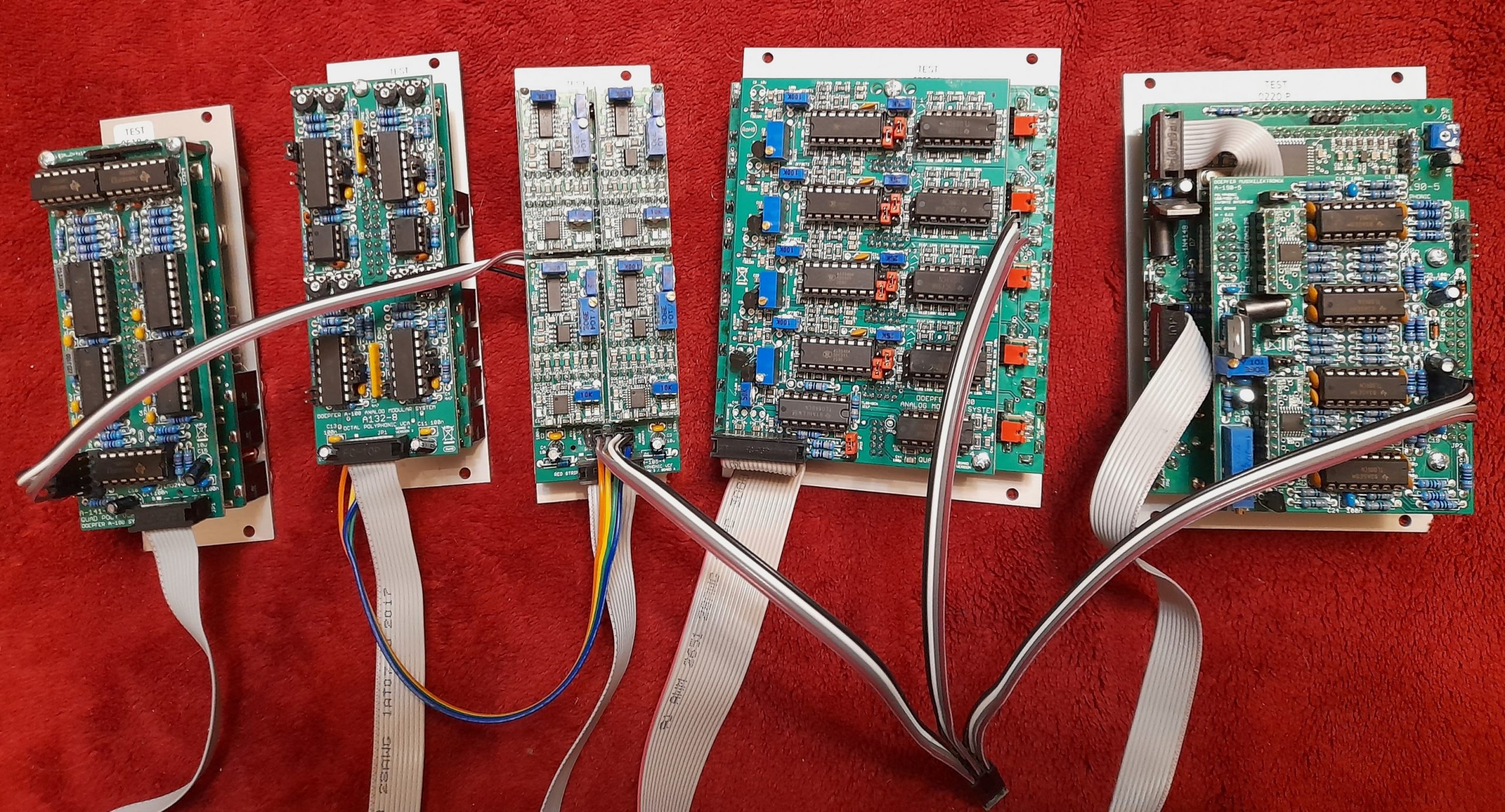
Looking behind the front panel, we then also see a circuit board for the closely populated sockets and potentiometers, behind it the actual main circuit board and on top of that the four actual filter circuit boards “piggybacked”.
Possible applications
Can a polyphonic A-100 replace one of the modern polyphonic synthesizers? Or even surpass it?
That depends on what you want.
On the one hand, we are limited to only 4 voices – more voices are possible in principle, but the system becomes much more cumbersome to use. The common control for all polyphonic Doepfer modules only includes 4 voices, with 8 voices you would have to adjust almost everything manually between two such “blocks of four”.
On the other hand, 4 voices are enough for many (really VERY many) purposes and there are options for intervention in each voice that no other synthesizer offers, e.g. a basically independent handling of pitch and trigger for each voice: One can be controlled by a keyboard (e.g. with the polyphonic midi interface A-190-5), the other by a sequencer like the A-157 trigger sequencer, which with its 8 tracks can also trigger the envelope curves of the VCAs and filters independently of each other.
When it comes to modulation options, there is of course stiff competition from poly-synthesizers with a sophisticated modulation matrix, but with the A-100 you are still a bit more flexible if you want it and if you are willing to put in a little more effort.
And yes, the “shortcoming” of almost all modular synthesizers also occurs in the polyphony: We cannot “save” any sounds. Instead, we learn where to reach to change something, we really and truly have a knob for each function and an individual instrument instead of a “preset slingshot” with an OLED display and knobs for any 4 functions.
This requires some planning in advance. So, as usual, let’s take a look at what the A-105-4 filter can do.
User interface
Inputs:

- CVF: Control voltage input for jointly controlling the cutoff-frequencies for all 4 filters.
- CVFM: Control voltage input for the intensity of the 4 “FM” inputs (individual control voltages for the 4 corner frequencies).
- CVQ: Control voltage input for controlling the 4 resonances (“Q”) of the filters together.
- CVL: Control voltage input for jointly controlling the input levels of the 4 filters.
- FM: Individual control voltage inputs for the 4 cutoff-frequencies of the filters.
- In: Audio inputs for the 4 filters.
Outputs:
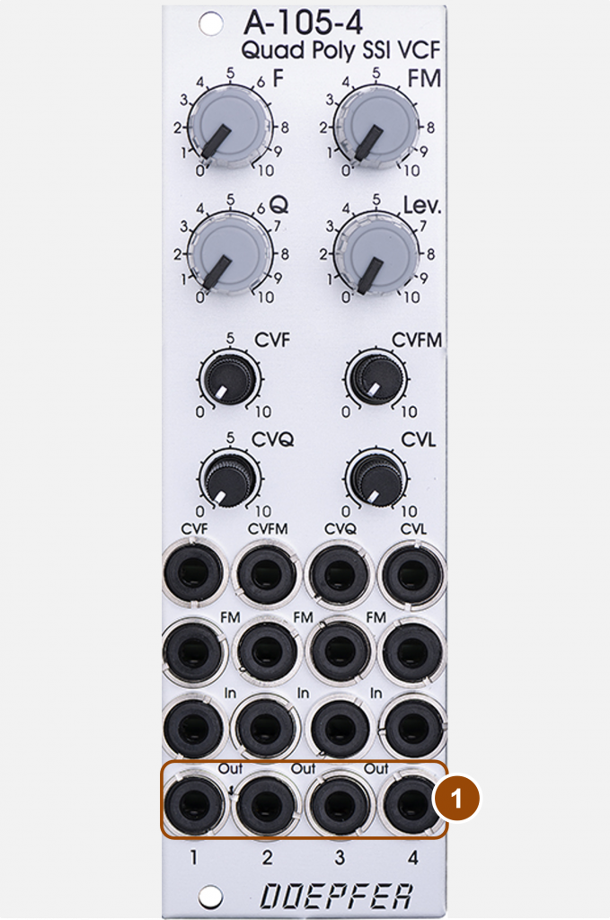
- Out: Audio outputs for the 4 filters.
Controls:
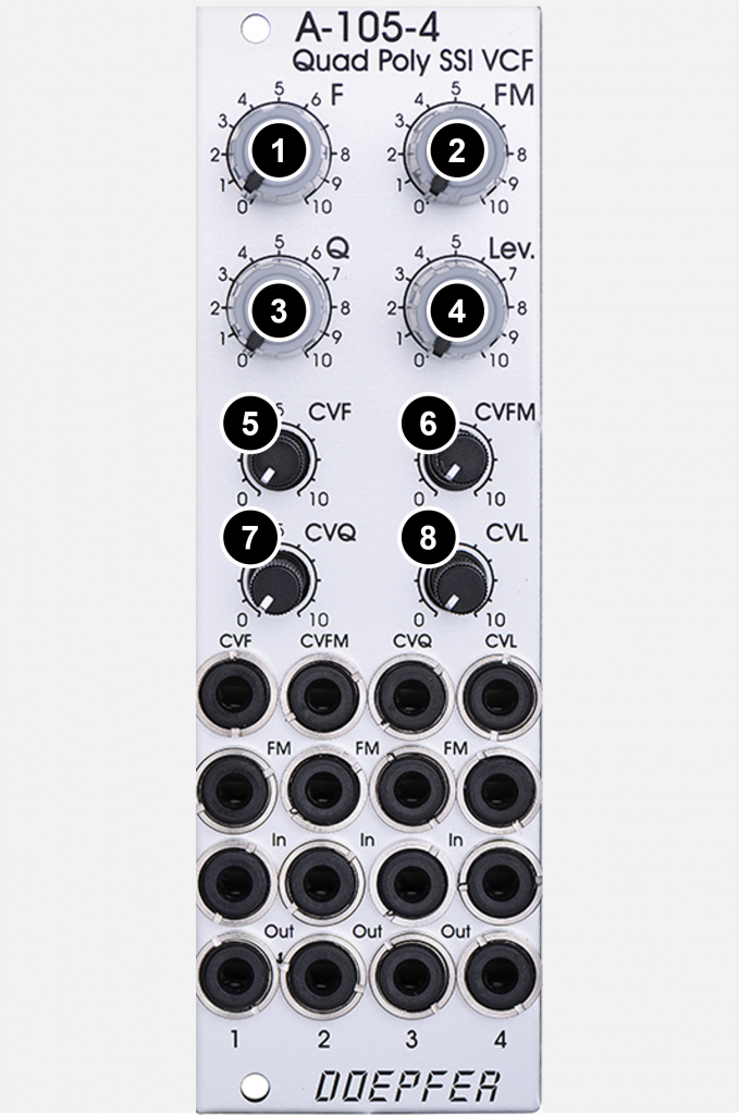
- F: Common controls for the cutoff-frequencies of the 4 filters.
- FM: Common controller for the frequency modulation intensity of all 4 filters via the 4 “FM” inputs.
- Q: Common control for the resonances of the 4 filters.
- Lev.: Common controller for the input levels of the 4 filters.
- CVF: Attenuator of the common control voltage for the cutoff-frequency of the 4 filters.
- CVFM: Attenuator of the control voltage at the “CVFM” input, which in turn regulates the intensity of the 4 individual “FM” inputs.
- CVQ: Attenuator of the common control voltage for the resonance (“Q”) of the 4 filters.
- CVL: Attenuator of the common control voltage for the input levels of the 4 filters.
This gives us 3 “global” control options – manually or via control voltages: The controller “F” or the input “CVF” for the corner frequency, “Q” and “CVQ” for the resonance as well as “Lev.” and “CVL” for the input level of the 4 filters installed in the A-105-4. The aim of a polyphonic filter is that all 4 filters behave the same or sound approximately the same.
In addition, there are 4 individual control voltage inputs for the cutoff-frequencies, which in practice will usually be fed with 4 ADSR generators, unless you want to implement more complex things via a matrix mixer (e.g. A-138m). In addition, there is now a fourth global controller “FM” and the control voltage input “CVFM”, which jointly regulate the modulation intensity of the 4 individual “FM” inputs for all 4 filters.
A minimal poly setup featuring the A-105-4
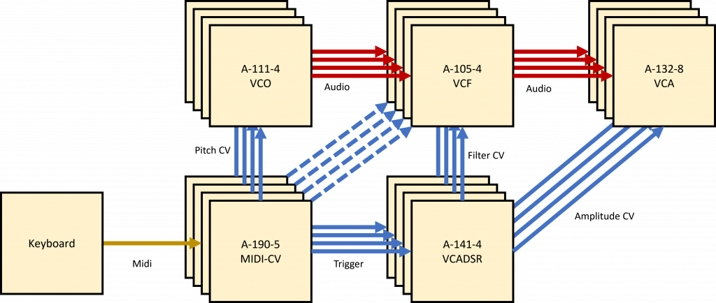
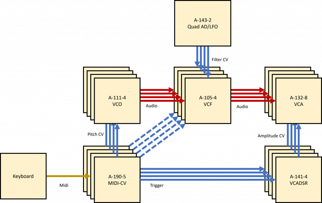
If we use an A-111-4 VCO as the sound source, then the outputs of the VCOs (e.g. the four sawtooth outputs) are connected to the four “In” sockets of the filter. Similarly, we connect the four “Out” jacks of the filter to the four “In” jacks of an A-132-8 Octal Poly VCA. So far no different than a monophonic filter module, just separately for each of the four voices.
Likewise, we can connect the outputs of an A-141-4 Poly VCADSR to the four “FM” inputs of the filter. A second A-111-4 could control the VCA, or we could split the outputs of a single A-111-4 via multiples and use the envelopes for the filter and amp at the same time, which I personally like to use.
The rest can be set manually or the top row of sockets that are still free can be used for control voltages that affect all four filters simultaneously: Filter cutoff frequency (“CVF”), intensity of the individual modulation by the ADSRs (“CVFM”), resonance (“CVQ”) and input level (“CVL”). The “CV3” outputs of the A-190-5 are ideal for this, which can be assigned e.g. with note-independent parameters such as aftertouch, modulation wheel, etc.
Thinking slightly more “modular”
Nobody forces us to use a polyphonic modular system the same way as a run-of-the-mill polysynth. On the contrary, this of course gives away some interesting possibilities.
For example, instead of a poly ADSR, you can assign the four individual CV inputs of the filter with four LFOs of different speeds, while the VCA is still “traditionally” controlled with an A-141-4. This is actually a totally banal variant, but it can only be realized with a few non-modular synthesizers.
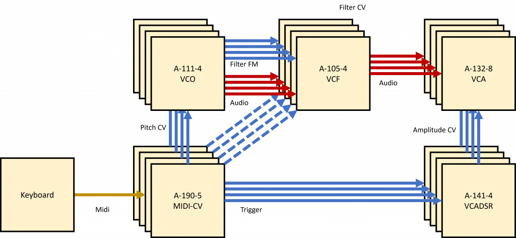
Filter FM at audio speed would be another very simple but effective example: the filter cutoff frequency is modulated by the particular oscillator being filtered. The sound spectrum lies somewhere between metallic and distorted and can be dosed quite sensitively with the A-105-4.
Ideally, the filter is also controlled by the control voltages for the VCO frequencies. Due to the filter tracking of – very close to – 1V/octave, the filters can take over a second VCO per voice in self-oscillation. (See below for details on filter tracking.)
Control options on the board
As is now customary at Doepfer, there are also some interesting intervention options for the A-105-4 via jumpers on the module’s circuit board. The main focus here is on the pre-wiring of a polyphonic system without having to use patch cables on the front panels of the VCOs or VCAs involved.
- CV inputs for frequency modulation of the filter (double)
- Four individual audio inputs
- Four individual audio outputs
The connections to the A-190-5, to the A-132-8 Poly VCA (individual outputs of the A-105-4) and e.g. to the A-141-4 ADSR (modulation inputs of the filter) are made with female-female jumper cables.
Filter tracking
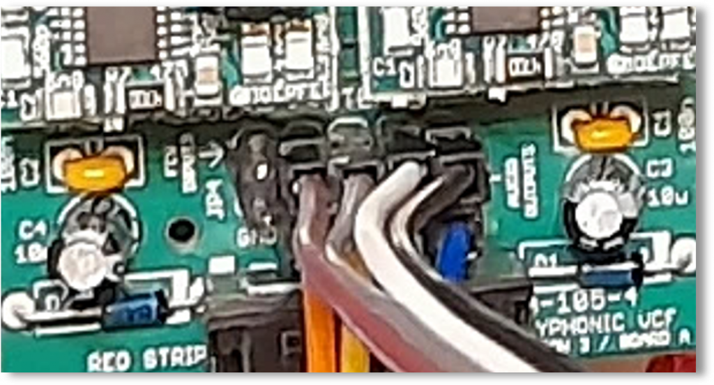
The modulation inputs on the board are ideal for realizing filter tracking: Simply connect the four CV outputs of the A-190-5 midi interface to the FM inputs of the filter (top row of connector strip JP4). Conveniently, the modulation inputs work in addition to the mini jack sockets on the front panel, so that no modulation options are “wasted”.

Unfortunately, the CV outputs of the A-190-5 have now been “installed”, which are then no longer available for controlling the VCOs. Doepfer has a small mini circuit board with 12 pins that can be used as “micro multiples”: Four (female) jumper cables can be split into 2 x 4 additional jumper cables with the tiny circuit board. The A-190-5 has buffered CV outputs so that the distribution of the control voltages does not cause any problems.
Filter FM again
From version 2 of the filter there are four more pins on JP6 for the filter FM. However, they are not additive like on JP4, but allow a default assignment of the four “FM” switching sockets. A connection to the A-141-4 ADSR is a good idea here, which can be replaced with patch cables on the front panel if required.
The control voltage inputs were already accessible on the circuit board in the first version of the A-105-4 – but here you still had to use a soldering iron.
Default inputs and outputs
On the lower row of JP4, the individual outputs of the filter can be connected to the A-132-8 VCA, for example (only available from version 2 of the filter).
In addition, the four audio inputs of the filter are available with JP7. If you only use a single A-111-4, you can easily pre-assign jumper cables to the “In” sockets of the A-105-4. In the first version of the module, there were only solder points for this.
For the other four control voltage inputs CVL, CVQ, CVFM and CVF, there are solder points for preassigning the switch sockets on the front panel if required.
Example: Simple cabling of a polyphonic synthesizer
For a simple poly system I connected the CV outputs of the A-190-5 to the CV inputs of an A-111-4 and the A-105-4 (for filter tracking) via micro-multiples. In addition, the ADSR control voltages of an A-141-4 are connected to the default inputs of the filter – can be interrupted at any time via the sockets on the front panel.
The individual audio outputs of the filter are also connected to the default audio inputs of the A-132-8 VCA.
Sound examples
-
A-105-4 / Quad AD/LFO controls the filters
The pulse outputs of an A-111-4 are modulated in pulse width by the 4 outputs of an A-143-9 QLFO. The A-105-4 filters are not modulated by an ADSR, but by the outputs of an A-143-1 Complex Envelope Generator (all EGs in LFO mode). The four sub-modules of the A-143-1 are randomly restarted (but synchronized by a common clock) by four trigger outputs of an A-149-2. An A-141-4 traditionally controls the A-132-8 VCA. Some reverb and delay from the DAW.
Filter control by the A-143-1. -
A-105-4 / Filter FM through the VCOs
The triangle outputs of an A-111-4 are filtered by the A-105-4. The sawtooth outputs of the A-111-4 are connected to the “FM” inputs of the A-105-4 as modulation sources. In addition, the cutoff-frequency is controlled by the “CV Note” outputs of the A-190-5 midi interface. An A-141-4 and the four velocity outputs of the A-190-5 control the subsequent A-132-8 VCA.
Further modulations: A slow A-143-9 modulates the corner frequency of all 4 filters, another slow A-143-9 controls the resonance and input level of the four filters. The velocity outputs of the A-190-5 also control the four linear VCAs in the A-132-8.
Filter FM. -
A-105-4, A-130-8 / Filter FM again
Here I use the sawtooth outputs from the A-111-4 as sound sources, this time the filter FM is handled by the triangle outputs. These are now modulated in amplitude by the envelope signals of the A-141-4 using an A-130-8 Octal Linear VCA before they go into the A-105-4. I tweak the resonance, input level and overall FM of the filters manually. Delay and reverb again from the DAW.
Filter FM again. -
A-105-4 / Unisono
Why not use the polyphonic modules monophonically – “unisono”?
The A-190-5 interface is not set to “poly” this time, but to “unisono”. This means that every midi note is output to all 4 VCOs, chords are not possible. Now one VCO of the A-111-4 is transposed an octave up and another one octave down. We use the pulse outputs, the pulse width is modulated by an A-143-9. The A-105-4 filter is modulated (in addition to the internally pre-patched tracking) by the A-141-4 envelopes and by a second A-143-9. For this I use two A-130-8 as “polyphonic mixers”. Both A-143-9 are additionally controlled by the note CV of the A-190-5. The sequence comes from an Arturia KeyStep 37, reverb and echo from the DAW.
This time the envelopes are not from the A-141-4 Poly-ADSR, but from two A-140-2 Dual ADSRs and are set slightly differently for each voice.
Unisono.
Further sound examples with clear participation of the A-105-4 can be found in the post on the A-132-8.
Technical specifications
| Width | 8 HP |
| Depth | 50 mm |
| Power requirements | 70 mA (+12V) / -70 mA (-12V) |