The module is no longer in production.
The A-107 was basically an Xpander filter (A-106-6) with greatly expanded filter modes (36 instead of “only” 16) and a digital control for morphing between different filter modes. The filter itself is of course purely analog.
The A-107 works with “filter chains”: Such a chain consists of a series of 32 filter modes that can be “passed through” in stages. Trigger inputs (“Step Clock” for the next step or “Step Reset” for returning to the first step) are used to switch to the next programmed level. Alternatively, CV inputs can be used to switch – the higher the control voltage, the higher the selected stage in the filter chain.
The transition between stages can be controlled from hard switching to slow “morphing” (also via control voltage or manually).
The filter types can be prepared and saved as a “chain” in practically any order. When changing between filter types with self-oscillation (No. 1-18) and those without self-oscillation (No. 19-36) only hard switching – and no morphing – is possible for technical reasons. 64 such “filter chains” can be saved permanently.
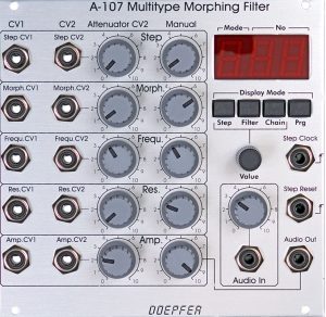
User interface
The filter has 5 sections for controlling its parameters, each of which has an identical structure:
- Step to control the position within the “Filter-Chain” (and thus for the selection of the filter mode).
- Morph determines the speed of the transition between the filter modes (controllable in the range from 0 to 5 seconds).
- The cutoff-frequency is determined via the Frequ. section.
- The Res. section is used to control the filter resonance.
- With Amp. the amplification of the filter can be influenced (via a VCA, which is at the output of the filter) – this is quite useful, since the filter modes are partly different loud for technical reasons, and you can still make adjustments here.
Inputs:
Control inputs for the 5 parameters:
The 5 parameters all have the same controls – 2 CV inputs each, an attenuator for CV2 and a manual controller.
- CV1: Control voltage input for the corresponding parameter (without attenuator).
- CV2: Control voltage input with attenuator.
Other inputs:
- Step Clock: Input for a trigger / gate signal that switches to the next filter mode in the programmed “filter chain”. At the end of the chain, the first step is started again.
- Step Reset: Input for a trigger / gate signal that resets to the step within the “filter chain” that is determined by the applied control voltage (or the manual “Step” control).
- Audio In: Input for the audio signal to be filtered.
Outputs:
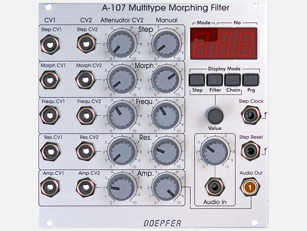
- Audio Out: Output for the filtered audio signal.
Controls (Display Mode and Programming):

Controlling the 5 parameters:
- Attenuator (attenuator) for the control voltage input “CV2”.
- Manual: Manual controller for the corresponding parameter.
Display mode and programming:
(See elements at right.)
So-called “chains” can be created with the programming section: These are fixed sequences in which a filter type can be set for each of the 32 “steps”. A small digital stepsequencer for filter types, so to speak. Up to 64 such “chains” can be stored in the module’s memory and retrieved later.
The display and the buttons below are used to program the chains. They can be used to select the current step in the loaded chain, set the filter type for that step, load prepared chains from memory, and save an edited chain to memory. The “Value” encoder below is used to select the step (from 1 to 32), to specify the filter type (from 1 to 36) for the current step and to select the memory location (from 1 to 64) when loading or saving a complete Chain.
- With the Step button, the number of the currently selected step (1-32) is shown in the display (above) (“S” and a two-digit number).
- Filter shows in the display the filter type of the current step (“F” and a two-digit number from 1 to 36).
- Chain allows you to load one of the 64 saved “Filter Chains”. “C” and a two-digit number of the last loaded “Filter-Chain” appear in the display.
- With Prg you can store an edited “filter chain” permanently on one of the 64 memories. “P” and a two-digit number of the “Filter Chain” last saved appear in the display.
- The Value controller (rotary encoder) is used to set the step, filter type or memory location for loading or saving the chains – depending on the selected operating mode.
- The Audio In controller is an attenuator for the audio input of the filter.
To program a chain, first press Step and use the Value knob to set the step number “S.01”. Then press Filter and use the Value knob to choose the type of filter you want for this first step. Then it’s back to Step again, you set the step number “S.02”, choose the filter type, then the next step follows and so on.
To save the chain you just created, briefly press “Prg” and set the storage location number for this chain with the Value control. By pressing “Prg” again for at least 1 second, the chain is then stored in the desired memory location.
Loading a chain works in the same way: Briefly press “Chain” and use the value control to select the desired storage location number. By pressing “Chain” again for at least 2 seconds, this chain will then be loaded and can be used.
Possible uses
The filter is predestined for sequencer-controlled crossfades of filter types. Filter morphing sounds interesting throughout, but usually not as spectacular as e.g. wavetable sequences or drastic sonic interventions with BBDs or waveshapers.
Alternative: A-106-6
If you can do without the digital control and are only interested in the – very good – basic sound of the filter, then the A-106-6 module is an excellent alternative. A look at the required power supply of the A-107 (200 mA is significantly more than any VCO needs) and the ample 26 HP might make the slimmer A-106-6 filter the better choice for smaller systems.
Both filters work with the same analog filter circuitry, the later released A-106-6 dispensed with the complex and expensive digital control (and some of the filter modes) in order to offer a more cost-effective variant of the A-107 filter.
16 filter modes are also a guarantee for versatility, even if the A-107 still has one or the other “delicacy”, for example in the form of the filter type “9”, which is visually reminiscent of the logo of a well-known fast food chain.
On the other hand: The A-107 filter was a rarity that raised the possibilities of filter circuits to an extremely high level. The following tables show which filter modes from the A-107 are also available in the smaller A-106-6.
Filter modes with self-oscillation:
| Nr. | Filter type: | A-106-6: |
|---|---|---|
| 1 | 24 dB lowpass | 4L |
| 2 | 12 dB lowpass | 2L |
| 3 | Bandpass (6 dB lowpass, 6 dB highpass) | 2B |
| 4 | Asymmetrical bandpass (12 dB highpass, 6 dB lowpass) | 2H1L |
| 5 | Asymmetrical bandpass (18 dB highpass, 6 dB lowpass) | 3H1L |
| 6 | Bandpass (12 dB lowpass, 12 dB highpass) | 4B |
| 7 | Notch + 6 dB lowpass | 2N1L |
| 8 | Allpass + 6 dB lowpass | 3A1L |
| 9 | 2 bandpass filters, separated by notch | / |
| 10 | Lowpass with shifted bandpass | / |
| 11 | Lowpass + notch I | / |
| 12 | “Tooth” (2 shifted bandpass filters) | / |
| 13 | Lowpass and two shifted bandpass filters (with different amplitude) | / |
| 14 | 2 bandpass filters with different amplitude | / |
| 15 | Lowpass + notch + highpass | / |
| 16 | Lowpass + notch II | / |
| 17 | Lowpass + soft notch + bandpass | / |
| 18 | Tiefpass + shifted bandpass (smaller amplitude) | / |
Filter modes without self-oscillation:
| Nr: | Filter type: | A-106-6: |
|---|---|---|
| 19 | 18 dB lowpass | 3L |
| 20 | 6 dB lowpass | 1L |
| 21 | 6 dB highpass | 1H |
| 22 | 12 dB highpass | 2H |
| 23 | 18 dB highpass | 3H |
| 24 | Asymmetrical bandpass (12 dB highpass, 6 dB lowpass) | 2H1L |
| 25 | 12 dB notch | 2N |
| 26 | Allpass (low frequencies attenuated) | 3A |
| 27 | Notch + highpass | / |
| 28 | Soft notch + bandpass filter shifted up | / |
| 29 | Allpass (high frequencies attenuated) | / |
| 30 | Highpass with “step” | / |
| 31 | Soft notch + bandpass filter shifted down | / |
| 32 | Lowpass + soft notch + bandpass | / |
| 33 | Notch + highpass | / |
| 34 | Lowpass + notch + highpass | / |
| 35 | Soft notch | / |
| 36 | Soft notch (variant) | / |
Sound examples
-
A-107, A-149-4 / Random Filter Morphing (Noise)
The raw material is colored noise from the A-118-1 Noise Generator processed with the A-107 Multitype Morphing Filter. The filter uses a filter chain of the first 32 filters (default). The filter is modulated by three slow triangle LFOs from an A-143-3 (CV1 inputs for morphing, cutoff-frequency and resonance), additionally by the four random voltages from an A-149-4 Quad VC Random Generator (CV2 inputs for step, morphing, cutoff-frequency and resonance). The A-149-4 is clocked for all four random voltages together by an A-146 LFO (positive square wave output).
Noise, randomly filtered.
Technical specifications
| Width | 26 HP |
| Depth | 40 mm |
| Power requirements | 200 mA (+12V) / -60 mA (-12V) |