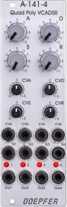
The A-141-4 is a quadruple ADSR that is only 8 TE wide and is primarily intended for polyphonic applications. Therefore, there is only one set of controls for the envelope’s parameters – attack, decay, sustain and release, which affect all four envelopes equally.
In addition, we find four control voltage inputs with bipolar attenuators for attack, decay, sustain and release – again for all four envelopes together.
The gate inputs are of course separate for the four envelopes…
User interface
Inputs:
Outputs:
Controls:
Polyphonic Voltage Control
In fact, for polyphonic use, being able to control all four envelopes with just one set of controls is incredibly handy. Especially when used to control the filters, you can hear small differences in the gradients quite quickly.
Voltage control is also a useful option, for polyphonic operation the four ADSR generators have to be regulated internally via control voltages anyway. But this is where there is still additional potential: Velocity (per note!) is one of the most important parameters for expressive playing on a polysynth. In addition to volume and filter, velocity can also be used for voltage-controlled envelopes. A light attack then leads, for example, to slow attack and decay times, a hard attack to very short attack and decay times (and perhaps to a longer release. For this, however, there would have to be an individual control voltage input for each of the four ADSR generators, connected to controls for how this control voltage affects the attack, decay and release of all four envelopes.
Something similar is built into the A-140-2, but only with one attenuator for all three times in common. But maybe in the future there will be a small additional module for the A-141-4 that contains the four control inputs (one per ADSR) and four attenuators (one per parameter, but common to all ADSR generators).
High output level
While the “old” A-140 ADSR still work with 0V to +8V, Doepfer has used a higher output level of 0V to +10V as the factory setting. This is compatible with the polyphonic A-132-8 VCA, but will clip an A-132-4, for example. This can be remedied by adjusting the A-141-4 to a lower level, the A-132-4 to a higher level, or an interposed quadruple attenuator, such as the A-183-5.
Configuration via the board
As with most of the newer Doepfer modules, we also find some jumpers on the A-141-4 to pre-configure the module to personal needs. And as with the other polyphonic modules, there are additional pins for pre-wiring with other poly modules.
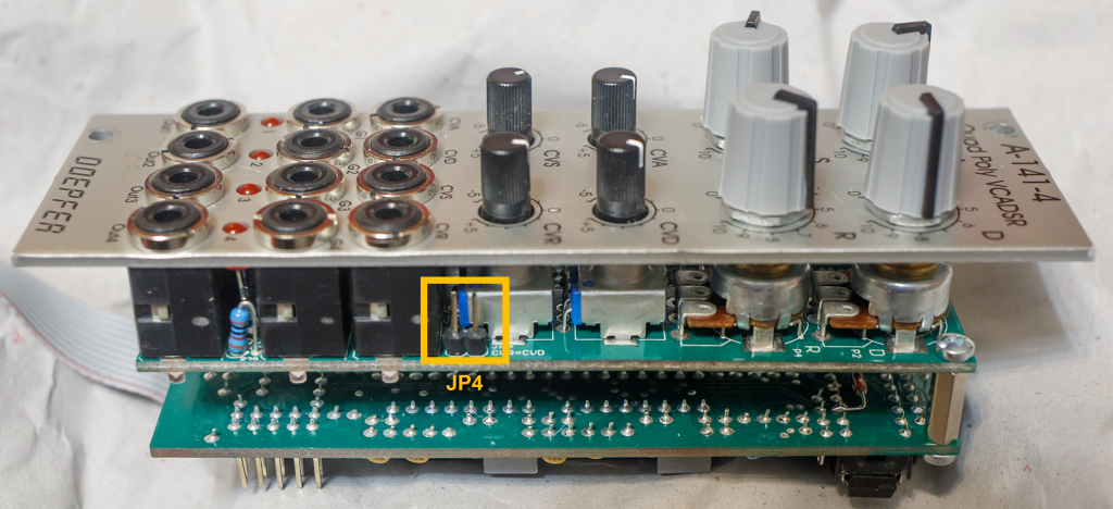
Release control voltage
With a set jumper JP4 on board B, the control voltage for the release time can be preassigned with the control voltage input for the decay time “CVD”. A patch cable in the “CVR” switching socket interrupts this pre-assignment.
Attack and decay control voltage
With the help of jumpers JP5 and JP6 on board B, the attack control voltage and the decay control voltage can be pre-assigned.
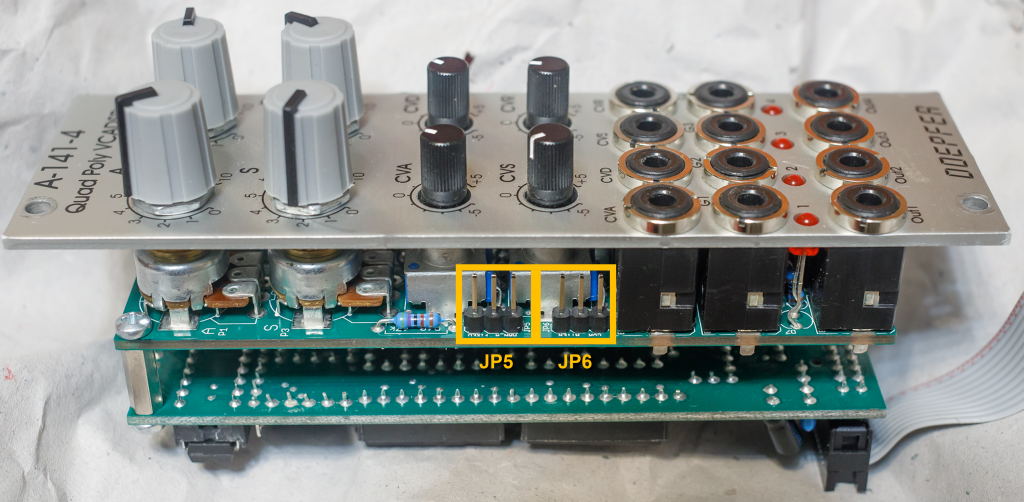
Attack – JP5:
- In the left position (on our illustration) the attack control voltage of the “CVA” input is pre-assigned to a constant voltage of 5V.
- In the right position (on our illustration) the attack control voltage of input “CVA” is preassigned with the control voltage from regulator “A”.
- Without jumper: No pre-assignment for the “CVA” input.
Decay – JP6:
- In the left position (on our illustration), the decay control voltage of the “CVD” input is pre-assigned to the voltage of the “CVA” input, namely AFTER the “CVA” attenuator.
- In the position on the right (in our illustration), the decay control voltage of the “CVD” input is pre-assigned to the voltage of the “CVA” input, BEFORE the “CVA” attenuator (i.e. independent of its position).
- Without jumper: No pre-assignment for the “CVD” input.
As usual, patch cables in the switching sockets on the front panel of the module override these pre-assignments.
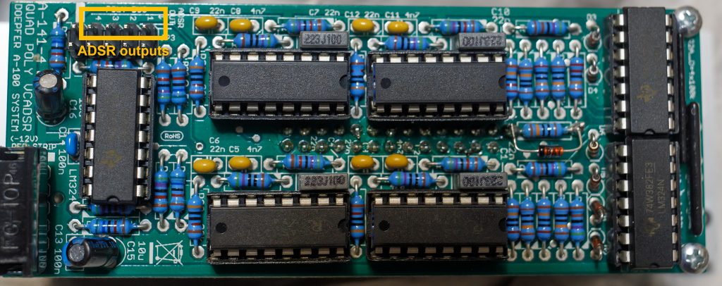
Polyphonic prewiring: ADSR outputs
The outputs for the ADSR control voltages for all four “voices” are available as pins on board A.
Polyphonic wiring: gate inputs
As of version 2 of the module, there are four pins on the underside of board B (i.e. between board A and B) for the pre-assignment of the gate inputs. The switching sockets on the front panel of the module can of course interrupt this pre-assignment.
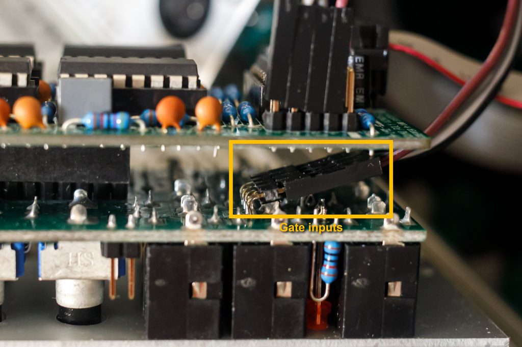
Attention: The labeling of the inputs on the circuit board is wrong with version 2. The pin on the very outside (here in the foreground of the picture) is actually the gate input for “Voice 4”, the pin on the very back is the gate input for “Voice 1”. The order printed on the board is inverted.
Sound sample – the “Doepfer patch”
In one of the first videos about the new polyphonic modules, Dieter Döpfer presented a very interesting patch in which the pitches of the VCOs were controlled by a keyboard, but the gates for the envelopes were generated by the A-157 Trigger Sequencer.
My setup is based on that, but instead of the polyphonic A-111-4 VCO and the polyphonic A-105-4 VCF, I use conventional A-110-1 and A-111-1 VCOs in conjunction with an A-120 Ladder Filter, an A-101-1 Steiner Filter, an A-106-5 SEM Filter and an A-124 Wasp Filter – with different numbers of VCOs and different waveforms as input signals.
In addition, the remaining four tracks of the A-157 trigger an A-142-4 Quad Decay, which again modulates the four length or level parameters of the A-141-4. Apart from that, I just play around on the keyboard to change the pitches and manually change the decay times of the A-142-4 and the ADSR parameters of the A-141-4.
The four voices are distributed in the stereo panorama, some VTape Delay and Valhalla Reverb on top.
Technical specifications
| Width | 8 HP |
| Depth | 45 mm |
| Power requirements | 70 mA (+12V) / -60 mA (-12V) |
| Output level | 0V … +10V |