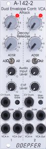
The module is small and interesting. A stripped down to two parameters but still flexible envelope generator with voltage control, hardwired to a linear VCA, plus a ducking function. The whole thing is also designed twice on only 8 HP. This is made possible by the new “Slim Line” format with slightly smaller buttons and sockets that are fixed to the front panel with very narrow nuts.
With the “Slim Line” modules, the switches and buttons are always on the top and the sockets are on the bottom. This makes it a bit easier to operate in the confined space.
This is one of those tools that aren’t particularly spectacular, but are extremely useful for smaller setups when you’ve run out of VCAs and ADSR generators for more complex patches. And who hasn’t that happened to?
The module number A-142-2 indicates a relationship with the A-142-1 and A-142-4: Both are single (or quadruple) decay envelopes, which are also good additions to the “big” A-140 and A-141 ADSR generators. Sometimes you don’t need all the complexity of an ADSR envelope.
User interface
Inputs:
Outputs:
Controls:
Envelope modes
The type of envelope can be set separately for each of the two sub-modules:
- AD: As long as the gate signal is active, the attack phase is run through first, followed immediately by the decay phase. For the decay phase itself, it is irrelevant whether the gate signal is still active or not. If attack is set to 0, this operating mode behaves like the decay generators in the A-142-1 and A-142-4, the envelope can then be started with a very short trigger signal.
- ADSR: As long as the gate signal is active, the attack phase and immediately after that the decay phase run through until the envelope finally remains at a fixed sustain level of 50%. At the end of the gate signal, the release phase starts, which has the same length as the decay phase. You know that from the envelope curves in the Minimoog.
- AR: As long as the gate signal is active, the attack phase is run through, then the envelope remains at a level of 100%. At the end of the gate signal, the release phase starts.
If the duration of the gate signal is shorter than the set attack time, the attack phase is terminated prematurely in all operating modes. The envelope curve then goes directly into the – also shortened – decay or release phase. The internally generated voltage has not reached its maximum level and is also being discharged to 0 volts more quickly.
Ducking
“Ducking” is more familiar from audio signal processors, where, for example, whenever the bass drum is played on one audio channel, the volume of another audio channel (e.g. with the bass) is specifically reduced until the bass drum has faded away again. Even with radio broadcasts, the volume of the music is automatically turned down as soon as the presenter speaks.
The A-142-2 has a “CV Duck” control voltage input that is designed for an input range of 0 to +5 V. As the voltage rises, the volume of the VCA is progressively reduced until the VCA is completely muted from +5 V.
Internally, this control voltage (inverted and amplified by a factor of 2) and the control voltage generated by the envelope (0 to approx. +10 V) are mixed before they control the VCA. With +5 V at “CV Duck” the VCA is initially controlled with -10 V and does not get more control voltage than 0 V even at the maximum level of the envelope. A normal VCA does not react to negative control voltages, so it remains mute. Incidentally, the LED on the front panel only shows the course of the envelope curve, not the modulation of the VCA including the ducking control voltage.
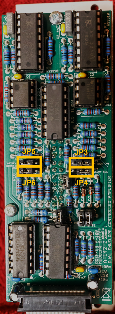
Configuration options on the board
Like almost all newer Doepfer modules, the A-142-2 can also be configured via jumpers on the circuit board.
Control voltages for the envelope times
For both attack and decay/release, it can be set separately whether a positive control voltage at the “CVT” input lengthens or shortens the times. Attention: The respective jumper positions for the left and the right sub-module are arranged mirror-inverted. JP3 and JP4 are therefore factory-fitted on the right, JP4 and JP5 on the left.
| Jumper: | Position: | Impact: |
|---|---|---|
| JP3 | right* (default) | higher control voltage = longer attack time of the left** sub-module |
| left | higher control voltage = shorter attack time of the left sub-module | |
| JP4 | right (default) | higher control voltage = longer decay/release time of the left sub-module |
| left | higher control voltage = shorter decay/release time of the left sub-module | |
| JP5 | left (default) | higher control voltage = longer attack time of the right sub-module |
| right | higher control voltage = shorter attack time of the right sub-module | |
| JP6 | left (default) | higher control voltage = longer decay/release time of the right sub-module |
| right | higher control voltage = shorter decay/release time of the right sub-module |
** The “left” or “right” partial module when looking at the front panel from the front.
Gate signals from the A-100 bus
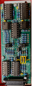
For both sub-modules it can be determined separately whether they are controlled via gate signals from the A-100 bus, such as those output to the bus by Midi interfaces. JP7 is responsible for the left sub-module and JP8 for the right sub-module. Without a jumper, the connection to the bus is interrupted.
Internal connection Envelope – VCA
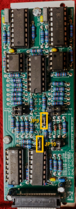
The internal connection between the control voltage output of the envelope and the CV input of the VCA can be broken separately for each sub-module. These connections are made at the factory via jumpers JP9 (left sub-module) and JP10 (right sub-module).
If necessary, you can replace one or both jumpers with so-called “jumper wires” (or “Arduino cables”), which e.g. distribute the output of an envelope to both VCAs so that they react exactly the same (e.g. for stereo applications). Or you can replace the envelopes with other envelopes or control voltages. Or you can also use the control voltage of the envelopes for another VCA or a filter: For this you need either a Y jumper cable or one of the micro multiples that Doepfer offers in connection with its polyphonic modules (these are mini circuit boards with 4 x 3 pins in which the pin triples are connected to each other).
The internal envelopes output a control voltage of 0 to approx. +10 V, externally applied alternative control voltage sources should also be able to do this in order to fully drive the VCAs, externally used targets for the control voltage should be able to process the +10 V without distortion.
Gate default
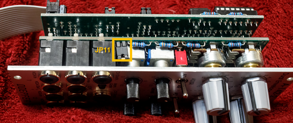
The gate input for the right sub-module is factory-connected to the gate input of the left sub-module. The connection can of course be broken via the switch socket at the “Gate” input of the right sub-module. This pre-assignment can be canceled by removing the jumper JP11 on board B (seen from the back of the module under board A).
Alternatives
The two most obvious alternatives are simple decay envelopes, which, however, do not have a VCA on board: The A-142-1 only has one envelope, which, in contrast to the A-142-2, is voltage-controlled in length. The A-142-4 has four such decay envelopes (without voltage control).
We find AD envelopes on the A-143-1, which offers four such envelopes with very sophisticated possibilities for mutual influence and mixing, but here too we need separate VCAs.
Another AD generator (and much more!) is the A-171-2 VC Slew Processor. It has separately voltage-controlled attack and decay phases, and can also work as an LFO, as a filter or as a slew processor for portamento.
The A-111-6 Miniature Synthesizer has an AD generator that is very similar to the A-142-2, including the option to switch to AR or an ADSR envelope with a fixed 50% sustain. Here, the envelope (which can be switched on and off) is connected to the VCA, external signals can also be processed.
Sound examples
-
Sound Example: A-142-2 / Noise sequence
A very simple “Percussion” setup: The audio signal for the left A-142-2 sub-module comes from an A-117 Digital Noise Generator, that for the right sub-module from an A-118-1 Noise Generator.
The gate signals are generated by an A-149-2 Digital Random Voltages, which is synchronized to the DAW via an A-149-1 and an A-190-8.
The two attack and decay times of the A-142-2 are modulated by the sine and inverted sine outputs from a slow A-143-9 quadrature LFO, the ducking inputs are fed with the sine and cosine outputs modulated from an A-110-4 Quadrature Thru Zero VCO.
During the sound sample I manually change the frequencies of A-143-9 and A-110-4, the noise rate in the A-117, the “white” and “red” parts in the A-118-1, and both attack and decay times in the A-142-2. It is mostly in “AD” mode, but I also switch to “ADSR” or “AR” mode from time to time.
From the DAW comes reverb, (synchronized) delay and chorus, the two “voices” are slightly distributed in the panorama.
Technical specifications
| Width | 8 HP |
| Depth | 45 mm |
| Power requirements | 60 mA (+12V) / -60 mA (-12V) |