Ratcheting controllers are still somewhat unusual tools in the modular world. Tangerine Dream already used them to create exciting sequences almost 50 years ago.
What does a ratcheting controller do? Basically we have the opposite of a clock divider (such as the A-160-2): An incoming clock signal is multiplied, if possible in such a way that the clock output also matches the original clock rhythmically and musically. In contrast to the clock divider, the electronics cannot simply “count” and e.g. emit a trigger signal itself for every fourth input trigger, but must take the average frequency of the input triggers into account and calculate its own – multiplied – trigger frequency from it. However, this also means that changes in tempo or fluctuations in the input frequency affect the multiplied clock signal: the A-160-5 needs a little more time to adapt to the new clock signal than a simple frequency divider.
Ratcheting
However, the actual ratcheting goes beyond a multiplication of the input clock signal. Otherwise you could simply choose a faster clock signal and then a simple clock divider for the slower variant (which serves as the input signal for our A-160-5). With ratcheting, however, only individual steps of a sequence are provided with a faster clock trigger and then it goes back to the original speed.
In order to control this automatically, the A-160-5 has a control voltage input: Here you can connect the sequencer itself or a random number generator running synchronously with the sequencer, which then determines the number of trigger pulses for each step of the sequence.
As the input clock signal for the A-160-5, you should actually use a clock trigger with a constant frequency and not one of the trigger/gate outputs of the A-155 sequencer: Omitting a trigger in the sequencer via one of the 8 control switches on the A-155 would otherwise throw the A-160-5 quite out of sync. However, you can omit individual sequencer steps completely, since the A-160-5 stops generating trigger signals if the control voltage at the “CV In” input is 0 V. If no voltage control is used: If the “Manual” control is turned completely to the left, the output of trigger signals also stops.
User interface
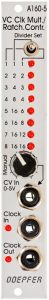
Inputs:
Outputs:
Controls:
Version differences
As already mentioned, the first edition of the A-160-5 had an incorrect labeling “Divider Set” instead of “Multiplier Set” next to the switch for the different multiplier rows. Doepfer has also eliminated a small error in interaction with a sequencer. In the first edition of the module, a changed control voltage did not have an effect immediately, but only on the subsequent sequencer step. Knowing this, it’s not a big deal, but the behavior of the current production A-160-5 is more convenient because more intuitive. It implements a changed control voltage immediately and not only in the subsequent step like the first edition.
Sound examples
An A-155 / A-154 sequencer controls an A-111-5 mini synthesizer. The clock signal from the A-154 is used as input clock for the A-160-5. The upper track of the A-155 controls (via an A-156 quantizer) the pitch of the A-111-5, the lower track of the A-155 is the control signal for the A-160-5’s ratcheting, which triggers the A-111-5‘s envelope. The control voltages for ratcheting are changed manually.
In addition to being used as a clock multiplier, the A-160-5 can also be used as an audio multiplier to a certain extent. An audio signal – ideally a square wave – is used as a clock signal, here from an A-110-1 VCO.
Technical specifications
| Width | 4 HP |
| Depth | 35 mm |
| Power requirements | 50 mA (+12V) / -0 mA (-12V) |