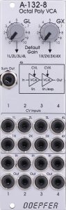
The A-132-8 is a module designed for polyphonic operation with 4 voices with a total of 8 VCAs. Why so many VCAs, one might ask, wouldn’t 4 be enough? Two VCAs connected in series are responsible for each of the four synthesizer voices on the A-132-8: The first VCA always works linearly, the VCA afterwards either linearly or exponentially (can be set via jumpers).
The first VCA will often be used for a common volume control or for touch dynamics, such as the polyphonic A-190-5 Midi-CV interface can provide for each voice as a separate control voltage.
The second VCA will in most cases be controlled by a (polyphonic) envelope generator like the A-141-4. An exponential VCA characteristic curve is then more interesting for many sounds, the tones “snap” more and have a somewhat more percussive effect. But since that is a matter of taste, you can also let the second VCA work linearly (factory setting).
If you don’t want to use an additional mixer (or four separate inputs in the DAW) for the four individual outputs, you can also tap a sum signal with all four voices.
The module is designed in “Slim Line” format and has slightly narrower controls and nuts for the sockets screwed to the front panel and only requires 8 HP.
User interface
Inputs:
Outputs:
Controls:
Configuration options on the board
As with practically all newer Doepfer modules, there are numerous configuration options via jumpers on the circuit boards of the module.
Characteristic of the second VCA group
While the four VCAs of the first amplifier stage always work linearly, the four downstream VCAs can be configured individually as linear or exponential VCAs.
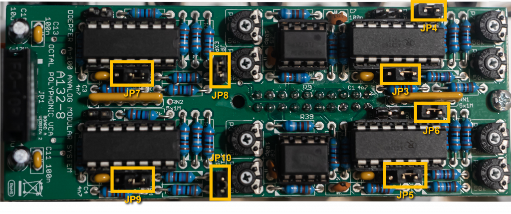
| VCA: | Linear: | Exponential: |
|---|---|---|
| X1 | JP5: bottom* JP6: open | JP5: top JP6: set |
| X2 | JP9: bottom JP10: open | JP9: top JP10: set |
| X3 | JP7: down JP8: open | JP7: top JP8: set |
| X4 | JP3: bottom JP4: open | JP3: top JP4: set |
* “bottom” and “top” according to the board labeling (rotated 90 degrees clockwise in the image above).
Default audio inputs
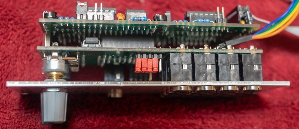
In order to save patch cables on the front panel, from the current version 2 of the module you can connect the four audio inputs via “jumper wires” (Arduino or Raspberry Pi cables with female-female connectors) with the polyphonic A-105- 4 VCF. The pins of jumper JP13 on the underside of board B, i.e. between board A and B, are used for this.
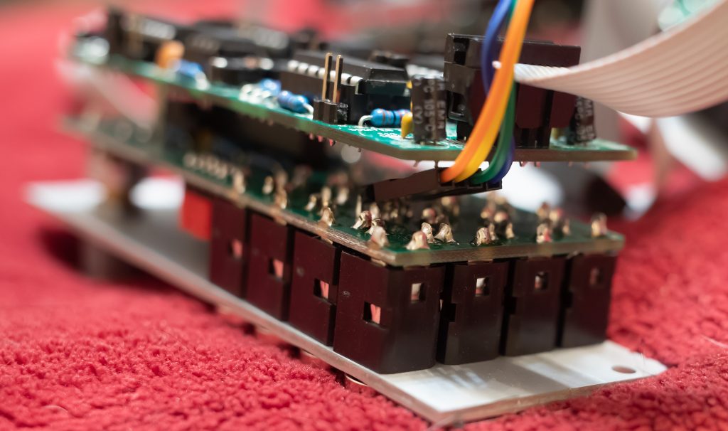
The space there is quite cramped. In order to be able to plug in cables at all, the pins were attached at an angle. This is a clever, practical solution!
Note: In the first version of the module, the audio inputs were still on the top of circuit board B and can only be reached by removing the front panel (= 2 rotary controls and 17 nuts for the sockets…).
Default modulation inputs
There are also pins for the four modulation inputs of the linear VCAs and also for the four modulation inputs of the linear/exponential VCAs on the top of board B, i.e. between the board and the front panel of the module.
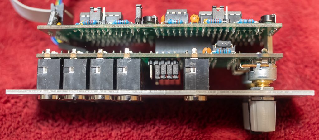
Note: The inputs for the linear working VCAs have been there since the first version of the module, the inputs for the linear/exponential VCAs X1-X4 were only added to the second version.
However, the pins have two special features:
- In order to get at this, you have to remove the front panel of the module. A special tool is advisable for unscrewing the 16 screwed sockets in the lower part of the module. Of course I was impatient and while clumsily tinkering I immediately “engraved” a fat scratch in the front panel… And even if you have taken this hurdle, the distance between the side with the pins and the front panel is relatively narrow, so that not every mini-plug will fit in terms of length.
- The pins are connected to the voltage of the “GL” and “GX” regulators via conventional jumpers. Just as a plugged-in patch cable deactivates the controller for the respective VCA via the switch sockets on the front panel, a jumper cable can only be attached if the jumper removed for this deactivates the connection to the “GL” or “GX” controller.
If the design needs to be revised again, it would be worth considering whether the two regulators “GL” and “GX” should not work additively with the external control voltages, as was the case with the A-132-3, for example.
The polyphonic A-141-4 envelope generator offers the pre-assignment of the four downstream linear/exponential VCAs. For the four linear VCAs, this would probably be the “CV2” outputs of the A-190-5 interface, which convert the velocity per note into control voltages. Here, however, the corresponding connectivity via the board of the midi interface is missing. But it doesn’t matter, the connection can also be made very easily using conventional patch cables.
Alternatives
In addition to the A-132-8, Doepfer has numerous other VCAs that can be considered for polyphonic use. The default audio inputs of the A-105-4 are then of course omitted and there is more “cable clutter” on the front panels. Otherwise, especially VCAs in a polyphonic context are rather unproblematic because there are only a few control elements that have to be changed at the same time.
A-132-4 Quad Exponential VCA
If you don’t need the upstream linear VCAs, you could use a very good quadruple VCA with an exponential characteristic in the form of the A-132-4. With only 6 HP, it is even a bit narrower and also has a sum output, which saves a final mixer. If you don’t need it, the socket for the sum output can be reconfigured as a second control voltage input, so that you have two modulation inputs available for all four VCAs.
The A-132-4 is factory configured for control voltages from 0V to +5V. However, the polyphonic A-141-4 ADSR generator delivers an output voltage of up to +10V, which clearly causes the VCAs to distort. Here you have to adjust the sensitivity via four trimming potentiometers on the board or patch a quadruple attenuator like the A-183-5 between ADSR and VCA.
A-130-8 Octal linear VCA
If linear VCAs are allowed, the eightfold A-130-8 can be used instead of the A-132-8. Like the A-132-4, it is also preconfigured for control voltages from 0V to +5V and can be adjusted to the higher voltage from the A-141-4 using trimming potentiometers. The A-130-8 also only requires 6 HP of rack space.
In addition to the individual VCA outputs, there are sum outputs for all eight VCAs, for VCAs 1-4 and for VCAs 5-8. The biggest advantage is the total of eight VCAs, so you can use two-stage amplification as with the A-132-8, or you can use VCAs 5-8 for other purposes, such as control voltages, which are then controlled by an A-141-4, for example. I use two A-130-8 as a polyphonic quad mixer for control voltages (and the A-132-8 as a polyphonic audio VCA).
A-135-2 Quad VCA/VC Mixer
Like the A-132-8, the A-135-2 is built in “Slim Line” format with narrower controls and jacks, the controls are also all at the top and the jacks are at the bottom, which provides a better overview in a rather small space . The VCAs all work linearly, the maximum control voltage is only 5V, but there are four attenuators for the CV inputs on the front panel.
In addition to the individual outputs, the A-135-2 as a mixer naturally has a sum output, or even two: a “normal” sum output and one that only contains the input signals whose individual output is not patched.
The biggest advantage are the four controls for manual adjustment of the levels independent of the applied control voltages. This is useful for drones, for example.
A-130-2 Dual linear/exponential VCA
The A-130-2 (a 4 HP wide “Slim Line” – offshoot of the A-132-3, which I really appreciate) is probably the closest to the A-132-8 in terms of functionality. With two A-130-2 you have four VCAs that can be individually switched between linear and exponential.
If you want it really “luxurious”, use 4 of them and, like the A-132-8, you get eight VCAs that can be switched between linear and exponential on the front panel. The price for this is (in addition to significantly higher costs for the modules) a space requirement of 16 HP and a multiple of cables.
The A-130-2 is also designed for control voltages of maximum +5V, but has attenuators for the control voltage inputs. In addition, if the control voltage is too high, it does not react by clipping the audio signal, but simply does not continue to amplify it. In the case of ADSR envelopes with fully open attenuators, this leads to a “hold phase” with a constant level between the attack and decay phases.
Like the A-135-2, the A-130-2 features “Gain” controls for manual control of levels independent of control voltage.
Sound examples
Linear vs. exponential
With all the theorizing about exponential vs. linear amplifiers, the question naturally arises as to whether you will even hear the difference. The two sound samples are intended to show these differences between the linear and exponential characteristics in the second VCA group. A bass sequence drives an A-111-4 VCO (sawtooth outputs), filtered by an A-105-4 and amplified by the A-132-8. The filters and VCAs are both controlled by the A-141-4 ADSR. The first (linear) VCA group of the A-132-8 is without modulation.
Decy and attack times are changed manually, sustain, release and all other parameters are the same in both examples. Some reverb and delay from the DAW.
Velocity sensitivity
I’m using the A-111-4 again, this time with its square outputs as the sound source. The pulse width is modulated by an A-143-4 Quad VCLFO – the LFO speed is controlled by the pitch CV from the A-190-5. The A-105-4 filter is modulated by velocity and pitch, but not by the ADSR. Finally, the A-132-8 is modulated by velocity in its first (linear) stage and by an A-141-4 in its second (exponential) stage.
During the sequence I tweak the VCF and ADSR, reverb and echo come from the DAW.
Technical specifications
| Width | 8 HP |
| Depth | 45 mm |
| Power requirements | 40 mA (+12V) / -40 mA (-12V) |