The long-awaited polyphonic mixer A-135-5 is now finally available since the end of 2023. Yes, of course you could already make do with A-130-8 VCAs, for example. Some poly fans also installed a series of A-138n narrow mixers or A-138f dual crossfaders, but of course it wasn’t all that elegant. The A-135-5 mixer is elegant.
What does a poly mixer do? Let’s assume we have two polyphonic A-111-4 VCOs that we want to use together to create a four-voice polysynth with two VCOs per voice, e.g. for each voice a sawtooth from the first A-111-4 and two octaves lower a triangle from the second VCO. In total there are eight signals that are mixed into four output signals (for further processing in the filter, for example). Usually with polyphonic synthesizers we want to set the mixing ratios the same for each voice. That’s why the A-135-5 has one controller that adjusts the level of four inputs (four voices) together: These are the input groups A, B and C and their controllers “Lev.A” to “Lev.C”. We connect the sawtooth outputs from our first A-111-4 to the four audio inputs “A”, the triangle outputs from the second VCO, for example, to the four audio inputs “C”.
With the “Lev.B” controller we can also use the internal frequency divider. It generates square wave signals one octave deeper from the four input signals from “A” (saw teeth in our example), as long as the “B” input sockets are unconnected. And if that’s not enough, you can stack two A-135-5s and mix up to 6 polyphonic sound sources. By the way, “polyphonic” here always means: four voices, just as all of Doepfer’s poly modules are designed for four voices.
What else is there? We also have a sum output if, for example, a paraphonic setup is the goal and the four VCO mixes are processed with a common monophonic filter or VCA. The three levels for the input groups “A” to “C” can not only be controlled manually, but also each have a control voltage input with an attenuator and also a “mute” switch for muting.
Anything else? Yes, the module is not only suitable for audio signals, but is DC-coupled and can therefore also mix interesting mixtures of control voltage sources (e.g. four LFOs, four envelope generators and four random voltages). This results in very versatile modulation signals in our Poly-A-100.
Despite its 10 HP, this is a module in the new “Slim Line” design: the controls are slightly narrower, all controls are at the top, the connection sockets at the bottom. This creates an overview even with full cabling and the operation is not restricted in any way, even for “fat fingers”, thanks to the reasonable controller spacing.
Controls
Inputs:
- Audio inputs A: Four audio inputs, e.g. for four VCOs, for the four sawtooth outputs of an A-111-4, but also, for example, for the four outputs of an A-141-4 Poly ADSR if you use the mixer for control voltages instead of audio signals. In this case you could mix the envelopes with four LFOs on the “B” inputs. The amplitude of the four inputs is regulated together via the “Lev.A” regulator or a control voltage.
- Audio Inputs B: Analogous to the “A” inputs, for example for a second A-111-4. If these four switching sockets are unused, the respective sub-octaves of channel “A” are generated for channel “B” and can be mixed with the input signals from “A”.
- Audio Inputs C: Analogous to the “A” inputs (in contrast to “B” without a frequency divider).
- CV Input A: Control voltage input for joint modulation of the amplitude of the four inputs “Audio Inputs A”.
- CV Input B: Same as “CV Input A”, but for the four inputs of “Audio Inputs B” or the suboctave of A if the “B” input jacks are not used.
- CV Input C: Same as “CV Input A”, but for the four inputs of “Audio Inputs C”.
Outputs:
- Audio Outputs: Four individual outputs for the mixes of “A”, “B” and “C” (e.g. two poly-VCOs on “A” and “C” and a mixer-generated sub-octave in channel “B”). This corresponds to the four individual voices, which can then be further processed in the A-105-4 Poly VCF, for example. If you use the module for control voltages, these are modulation signals for each of the four voices (e.g. Poly-ADSR, quadruple LFO and quadruple random for modulating the filter frequencies of an A-105-4).
- Sum: Sum output of all signals from the four voices.
Controls:
- Lev.A: Manual common control for the four levels of the input signals on “Audio Inputs A”.
- Lev.B: Same as “Lev.A”, but for “Audio Inputs B”.
- Lev.C: We “Lev.A”, but for “Audio Inputs C”.
- CV A: Attenuator for the control voltage at the “CV Inputs A” input, with which we can control the levels of the four input signals at “Audio Inputs A” together.
- CV B: Same as “CV A”, but for “CV Inputs B”.
- CV C: Same as “CV A”, but for “CV Inputs C”.
- Mute A: Switch to mute all four input signals on “Audio Inputs A”. Of course, you can also do this with the “Lev.A” control, but muting is always quicker and more precise with a switch.
- Mute B: Same as “Mute A”, but for “Audio Inputs B”.
- Mute C: Same as “Mute “A”, but for “Audio Inputs C”.
Possible uses
Audio mixer
The most obvious application is a polyphonic audio mixer, which is used before the (polyphonic) filter. This was the biggest logical gap in the polyphonic Doepfer modules so far: layering several A-111-4s and then processing them further with an A-105-4 poly filter. The mixer’s built-in frequency divider supports this use case: Even if you only have a single A-111-4 available, you can still generate a separate sub-octave for each voice with the A-135-5.
At this point you may ask yourself: Why is this thing linear if it is supposed to be used for audio? In fact, exponential mixers can be operated a little more “naturally” with audio material; the control paths correspond more to what you are used to hearing with volume progressions.
Voltage controlled mixing
Well, one reason may be that the A-135-5 is, last but not least, a voltage-controlled mixer: For automated crossfading (“morphing”), linear amplifiers are actually quite practical because the mixed sum signal can be more easily kept at a constant level if, for example, you use phase-shifted triangle LFOs for modulation. It is not without reason that the A-144 Morphing Controller, for example, requires a linear audio mixer: the sum of the signals always has the same level. When we use phase-shifted modulation with triangular signals, this is not possible with exponential mixers. And yes, you can also see the A-135-5 as a kind of polyphonic version of the A-135-2 VC mixer and use an A-144 morphing controller, for example, to control it, albeit only with three channels (instead of four).
Since the mixer has its own CV input for each channel “A” to “C”, you can easily create dynamic mixes using control voltages. As a matter of principle, the mixes are always the same for all four voices: This means that modulation sources that are intended to manipulate all voices together are particularly suitable. These are, for example, (monophonic) channel aftertouch, modulation wheel or a single, common LFO.
Things like touch dynamics, pitch or the envelopes of individual voices are less suitable: These are modulators that are designed to influence individual tones separately – but we only have modulation paths that work for all four voices at the same time. If you want to use such note-specific modulation sources, then the A-130-8 Octal Linear VCA – and a little more cabling effort – is the better choice.
Mixer for control voltages
Another reason for the linear design may be: The disadvantages of a linear mixer for audio material are comparatively small, but as soon as we begin to mix control voltages, we will no longer be able to adjust the modulations precisely (enough) with an exponential mixer – especially in the upper control range. Of course, this depends very much on the specific application; wild filter modulations are less sensitive than precise frequency modulations from VCOs…
Even the frequency divider becomes interesting again here: If an LFO (or a quadruple LFO) is fed into the “A” inputs, then you can mix in four square-wave LFOs with half the frequency via the unconnected “B” channel.
Configuration via the board
Cascading
Two A-135-5s can be cascaded via jumpers JP10 to JP13 and then mix up to six (four-part) input signals.
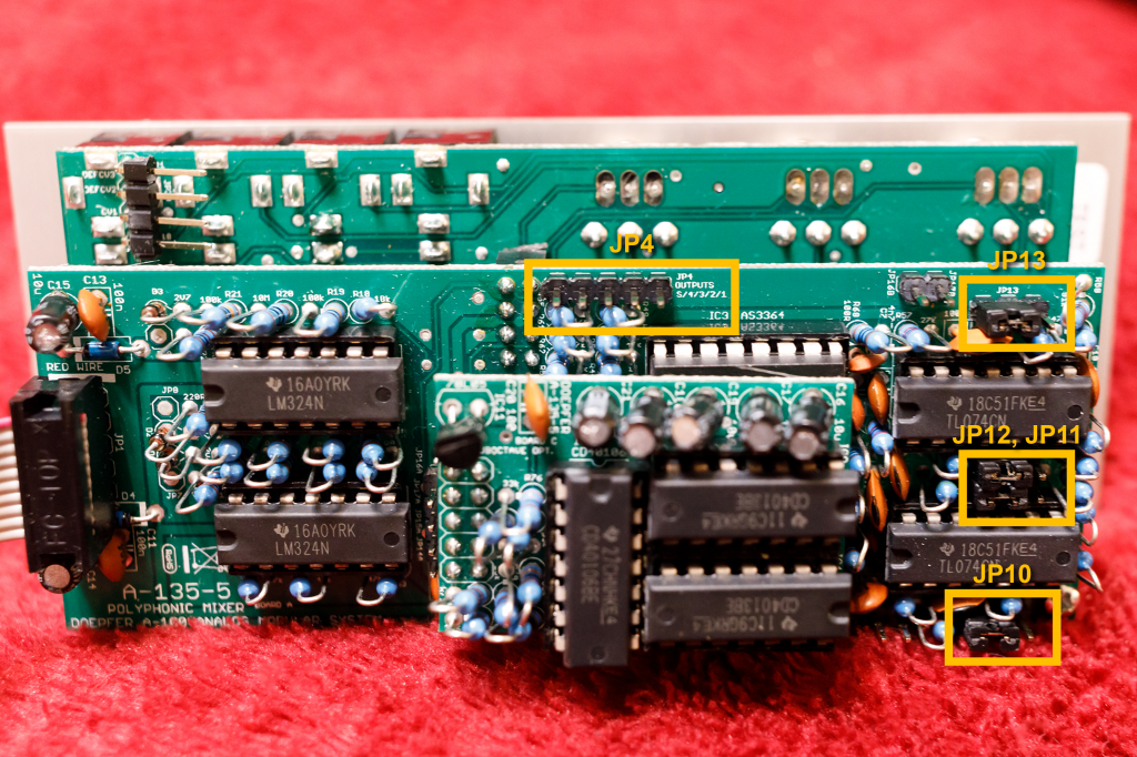
In the figure we see the jumpers and pins on board A, which still carries a small circuit board for the frequency divider. On the right in the picture are the jumpers JP10 to JP13 for cascading with a second A-135-5.
In the factory setting, jumpers are set on the left two of the three pins, the rightmost pin in the picture is free everywhere. To configure an A-135-5 mixer as a master, these four jumpers remain in place and jumper cables (“Arduino cables”) are plugged into the four free pins:
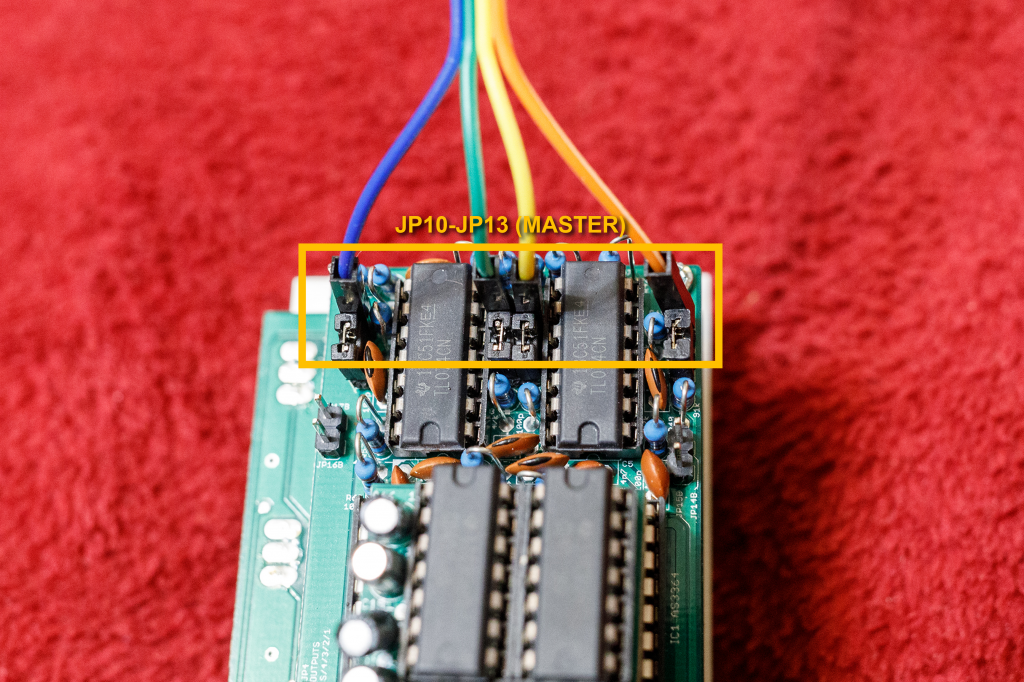
The master is the mixer module, whose outputs (Audio Outputs 1-4 and Sum) are used. Now we need a slave that contributes three additional input channels “A”, “B” and “C”, which are then also mixed into the master’s outputs. The outputs of the slave module are inactive.
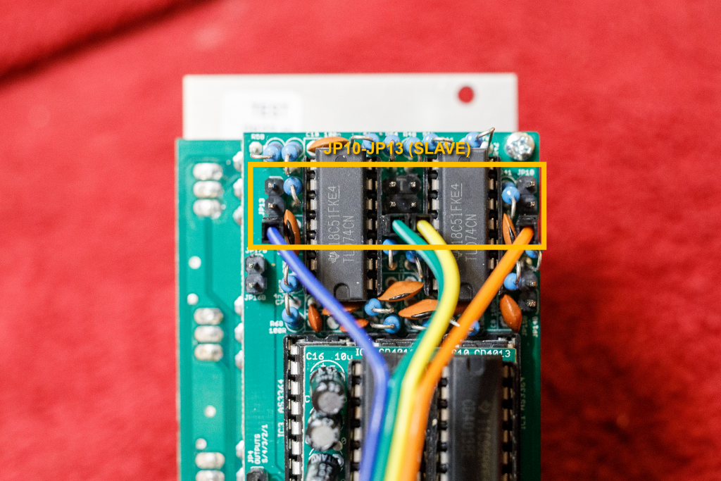
To do this, the four jumpers are removed and the other ends of our jumper cables are plugged into the pins that have become free – at the bottom in our illustration. The order of the cables must of course be the same as with the master mixer.
Internal pre-wiring – outputs
Let’s look again at the first photo of our board A. There is a pin header “JP4” with 5 pins:
This is where the outputs of the mixer are located, or in the case of a master/slave configuration, the outputs of the master mixer (the slave outputs are deactivated).
In our illustration these are from left to right:
- Sum output (mixing all four voices across all channels)
- Mixing all channels for voice 4
- Mixing all channels for voice 3
- Mixing all channels for voice 2
- Mixing all channels for voice 1
Internal pre-wiring – inputs
The mixer’s four “A” inputs and four “C” inputs can be preassigned via jumper cables to JP5 and JP6.
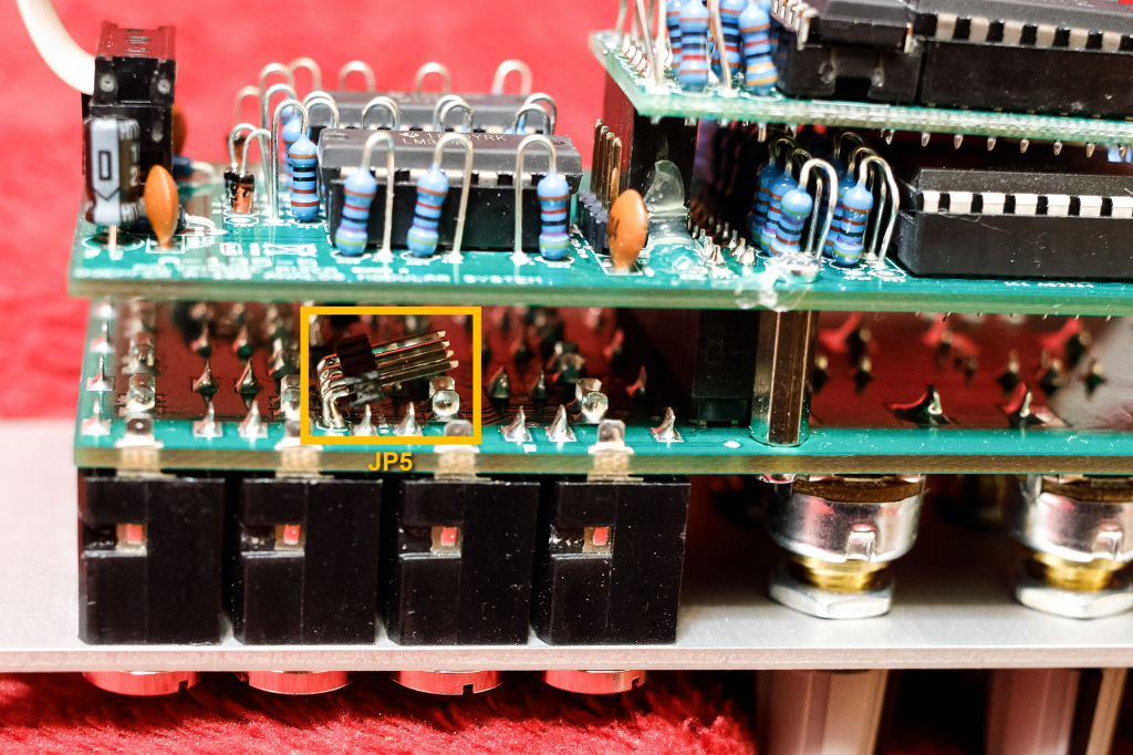
From the outside to the inside on JP5 these are the pins for the inputs of voices 1, 2, 3 and 4 for the mixer channel “A”.
… and on the other side of the board, also located under board A:
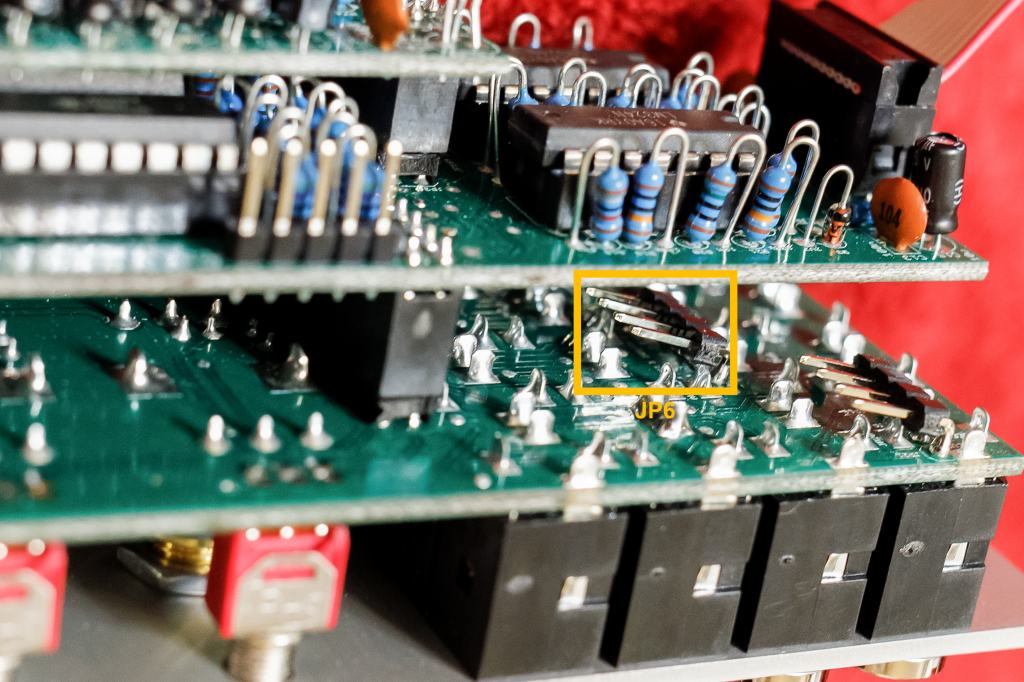
From the outside to the inside on JP6 these are the pins for the inputs of voices 4, 3, 2 and 1 for the mixer channel “C”.
Why not some “B” inputs as well?
They are already pre-assigned, namely through the small piggyback board of the four-fold frequency divider. If you definitely never want to use this frequency divider (e.g. because the module is used exclusively as a mixer for slow control voltages), then the board can be removed and you have four pins available on board A on jumper JP3A, to which you can also pre-assign the “B” inputs of the mixer externally.
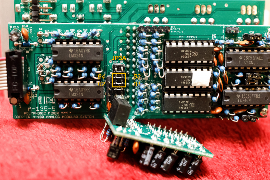
To correctly place the jumper cables for these inputs, you can use the pin header (JP16A, JP17A, etc., left of JP3A in the picture): There is NO pin to the left of the inputs for B3 and B4, to the left of the inputs for B1 and B2 is the first pin of this pin strip.
Since all 12 inputs of channels A, B and C on the front panel are designed as switching sockets, a pre-assignment is definitely interesting. For example, if you frequently use the saw teeth from two A-111-4 VCOs, you can pre-wire them and only replace them with triangle or pulse signals via conventional patch cables if necessary.
Pre-wiring of the control voltage
The control voltage inputs “CV Input A” to “CV Input C” can also be preassigned via jumper pins. On board B we find a pin header for the CV inputs (and a CV output):
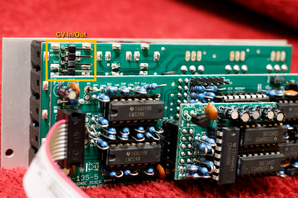
From top to bottom (in our photo) these are:
- Input for the control voltage of channel “C” (DEFCV3 – “Default CV 3”)
- Input for the control voltage of channel “B” (DEVCV2)
- Output of the control voltage from channel “A” (CV1) – ATTENTION, do not confuse it with an INPUT!
- Input for the control voltage of channel “A” (DEVCV1)
Alternatives
A-138n Narrow Mixer, A-138f Dual 3-way Crossfader
Some of the first Poly-A100 systems used four A-138n narrow mixers to mix multiple A-111-4s. Each narrow mixer has four inputs, each with an attenuator. You can live with that, but you have to set each of the four polyphonic voices manually. Advantage: Small (or even larger) differences in the mixes per voice enliven the overall sound. But: You can forget about quick changes in the mixing ratio this way, you just have to “screw” it manually for each voice. In addition, one A-135-5 only costs about as much as two and a half A-138n mixers (and only takes up the space of two and a half A-138n).
Things look a little different with the A-138f: Since this is a dual module, we only need two pieces and the price and space requirements are even cheaper than with the A-135-5. However, the functionality is also significantly limited: Although we only have a single control per poly voice (instead of four on the narrow mixer), we can only hear two of three input signals at the same time.
A-130-8 Octal Linear VCA
Until the A-135-5 was released, I used two A-130-8 Octal Linear VCAs and a modified A-183-5 quad attenuator (as a quadruple voltage source). This works very well, but is also significantly more expensive and is much wider in the rack than the poly mixer. Details can be found on the A-130-8. The main advantage was that this solution had been available for a long time and up to four channels (instead of the three “A” – “D”) are possible.
A-130-4 Quad VCA
A completely new module from Doepfer. No, not quite as new: The A-132-2 Quad VCA, which is twice as wide, is a direct predecessor, and the A-135-2 Quad VCA / VC Mixer is a much more complex alternative. The goal with the A-130-4 is not to create a polyphonic mix (multiple A-111-4 etc.), but simply to control four audio or control voltage signals together and as similarly as possible. So we have four inputs and four outputs (audio or CV) and a manual controller for all four signals in common, as well as a control voltage input for all four signals in common.
Advantage: Sometimes you don’t need a mixer at all, just a four-fold attenuator – controllable via CV, e.g. to control the intensity of a vibrato (on the A-111-4) or tremolo (on the A-132-8) via an envelope. With comparable modulations of the A-105-4 filter, you don’t need a separate A-130-4, the module has all control options “on board”.
Of course, neither the A-138n nor the A-138f or A-130-8 offer a frequency divider. Apart from the A-135-5, there are no quadruple frequency dividers. By the way, quadruple wave shapers are also missing…
Sound examples
-
A-135-5 / CV mixer for filter modulation
In addition to the obvious field of application as a polyphonic mixer for audio signals (poly-VCO mixer), the A-135-5 can of course also be used as a polyphonic mixer for control voltages. And even the built-in sub-oscillator/frequency divider doesn’t have to go unused…
I use two A-111-4 VCOs (sawtooth outputs), which this time are manually mixed with two A-138f crossfaders and further processed in an A-105-4 poly-VCF and an A-132-8 poly-VCA . Filters and amplifiers are each controlled by an A-141-4 Poly-ADSR. The ADSR for the filter modulation goes into channel “C” of the A-135-5, the ADSR for the VCA is connected directly to the Poly-VCA.
To modulate the filter, I also use the four square wave outputs of an A-145-4 quadruple LFO; they are connected to the inputs of channel “A” of our mixer. The LFO frequencies are slightly detuned so that each note has its own LFO frequency.
Some reverb and delay from the DAW.
I start with a pure ADSR modulation of the filter, then (from around 0:25) mix in the slightly different LFO modulations for each voice. And finally (from around 1:00) I open channel “B”, which halves the frequency of the LFO modulation voltages without its own input signal and gets a significantly more complex modulation of the filters.
Mix of a polyphonic filter modulation. -
A-135-5 / Two A-111-4 and suboctave
In this sound example, two A-111-4s are mixed with the A-135-5 poly mixer. The mixed signal is further processed in a polyphonic A-105-4 filter and an A-132-8 poly-VCA, the filter and VCA are each controlled by an A-141-4 poly-ADSR. The sequence is from an Arturia KeyStep Pro. Some reverb and delay from the DAW.
We first hear the first A-111-4 (sawtooth outputs), to which the sub-octave from the A-135-5 is slowly mixed in (from around 0:25). Afterwards (from approx. 1:10) the second A-111-4 is also faded in: square wave outputs, two octaves above the first A-111-4.
Finally, first the first A-111-4 is faded out and then the frequency divider signals from the mixer.
Mixture of two poly VCOs and the frequency divider of the poly mixer. -
A-135-5 / Random modulation
In this sound example I again use two A-111-4 VCOs (sawtooth and – two octaves higher – modulated pulse wave) at the inputs “A” and “C” of the A-135-5 poly mixer. A polyphonic sequence from the Arturia KeyStep Pro controls the synthesizer. The volume ratios between the VCOs and the sub-octave of the mixer are modulated by three random voltages from an A-149-4, the triggers for the random module come from the A-190-5. Some delay and reverb from the DAW.
Random modulation of the mixing ratios of poly-VCOs in the A-135-5. -
A-135-5, A-144 / Poly-VCO Morphing
This is once again an audio example in which I go close to the “self-destruction” of the sound through intensive modulation – the aesthetes may forgive me, sometimes I like it to be more extreme in terms of sound (and therefore musically only usable for “special cases”) . But maybe that’s still interesting…
Two polyphonic A-111-4 VCOs are mixed in the A-135-5 poly mixer, channel “B” produces the sub-octave in the mixer, channel “A” is sawtooth signals and channel “C” is triangle signals, two octaves higher . The mixer’s three modulation inputs (for “A”, “B” and “C”) are controlled by an A-144 Morphing Controller. It’s actually designed for four signals, so I have to manually adjust the modulation intensities until something useful comes out. The A-144 is modulated by a triangle output of the A-145-4 Quad LFO. This also generates negative voltages that the morphing controller does not expect: So an A-183-2 offset / polarizer is connected in between to compensate for this, so that the morphing controller is only controlled with positive voltages.
So a little bit of screwing and tinkering beforehand was necessary.
The VCO signals mixed in this way are further processed by an A-105-4 VCF and an A-132-8 Octal Polyphonic VCA, filters and amplifiers are modulated by two A-141-4 Poly ADSRs. The sequence comes from an Arturia Keystep Pro, which controls everything via the A-190-5 Midi-CV interface. Some reverb and delay from the DAW.
I start with a very slow modulation of the morphing controller, you can clearly hear the three different oscillators (or the frequency divider), the default level of the three mixer channels is set to 0. Then I slowly increase the frequency of the LFO that controls the morphing controller. At some LFO frequencies there is a nice interaction between morphing and the sequence. I increase the frequency even further until there are slight psychoacoustic effects such as an apparent increase in speed or later frequency – and at the end back to a very slow modulation speed.
Morphing two VCOs and the poly mixer’s frequency divider.
Technical specifications
| Width | 10 HP |
| Depth | 55 mm |
| Power requirements | 50 mA (+12V) / -40 mA (-12V) |