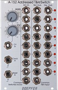
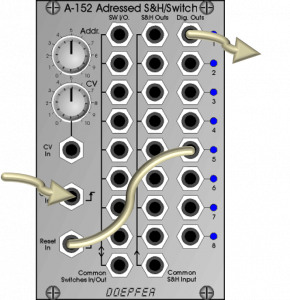
The A-152 Voltage Addressed Track & Hold / Switch module is by far the most flexible switching module presented here.
It offers a bidirectional 8:1 or 1:8 switch that can be addressed via control voltage as well as switched sequentially via trigger signals (or switched back to the first level with a reset trigger).
In addition, a Track & Hold (T&H) circuit with eight outputs is available, as well as a separate gate output (“Dig. Out”) for each of the 8 “stages”, which emits a gate signal when the stage is active.
The A-152 has written complexity of the possible applications all over it and is also a decent “cable eater” with its 29 sockets.
User interface
Inputs:
Outputs:
Controls:
Random gates
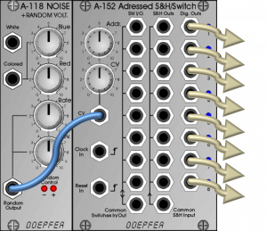
As an alternative to generating random gates with the A-149-1 / A-149-2, one can control the A-152 with a random voltage. In contrast to the A-149-2, only a single gate output at a time will be active. The circuit makes it possible to start several envelope curves independently (but never simultaneously) by random.
Switching of the outputs of an XP filter
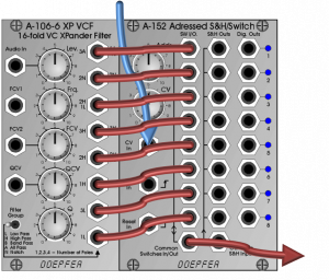
Similar to the A-155 sequencer, the switch can be used for rhythmically synchronized switching of the outputs of the A-106-6 XP filter. In contrast to the A-155, the A-152 requires significantly less space in the rack and is also noticeably cheaper.
Internal default connections
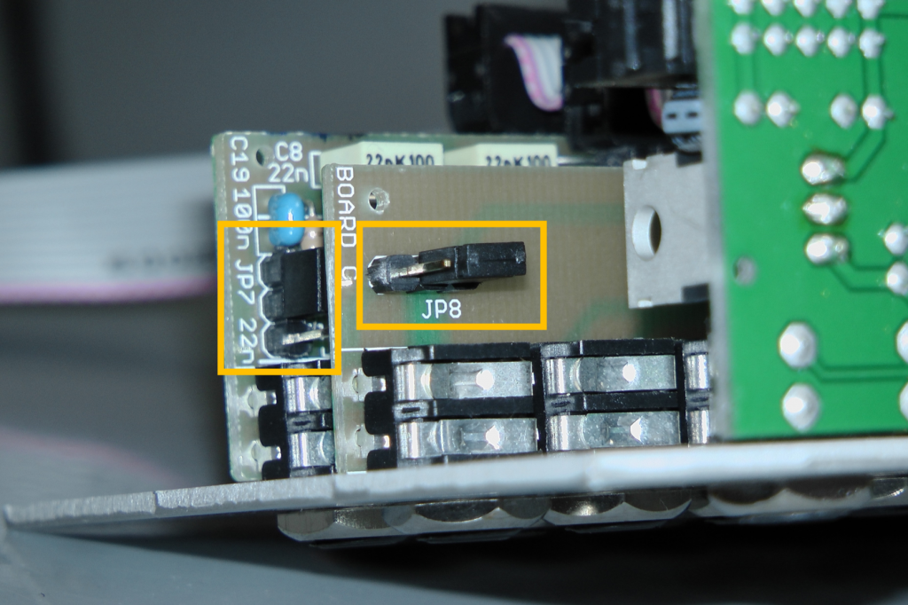
The two sockets “Common Switches In / Out” and “Common T&H Input” can be connected to each other via jumpers on the circuit boards.
- Variant 1 (default): Signals to “Common Switches In / Out” are forwarded to “Common T&H Input”. The connection can be interrupted if a plug is inserted into the T&H input socket (switching socket). This allows the use of 8 different input signals (via the “SW I/O” sockets) for the 8 T&H output sockets. To do this, jumper JP7 must be set on the pins facing away from the socket, jumper JP8 on the pins opposite the bottom edge of the board (as shown in the figure).
- Variant 2: Signals at “Common T&H Input” are forwarded to “Common Switches In / Out” (it serves as an input socket). The connection can be interrupted if a plug is inserted into the switch input jack (switching jack). This means that the T&H input signal is always available at the active output of the switches. To do this, jumper JP7 must be placed on the pins facing the socket, and jumper JP8 on the pins at the lower edge of the circuit board.
If both jumpers are removed, neither of the two sockets will receive the signal from the other.
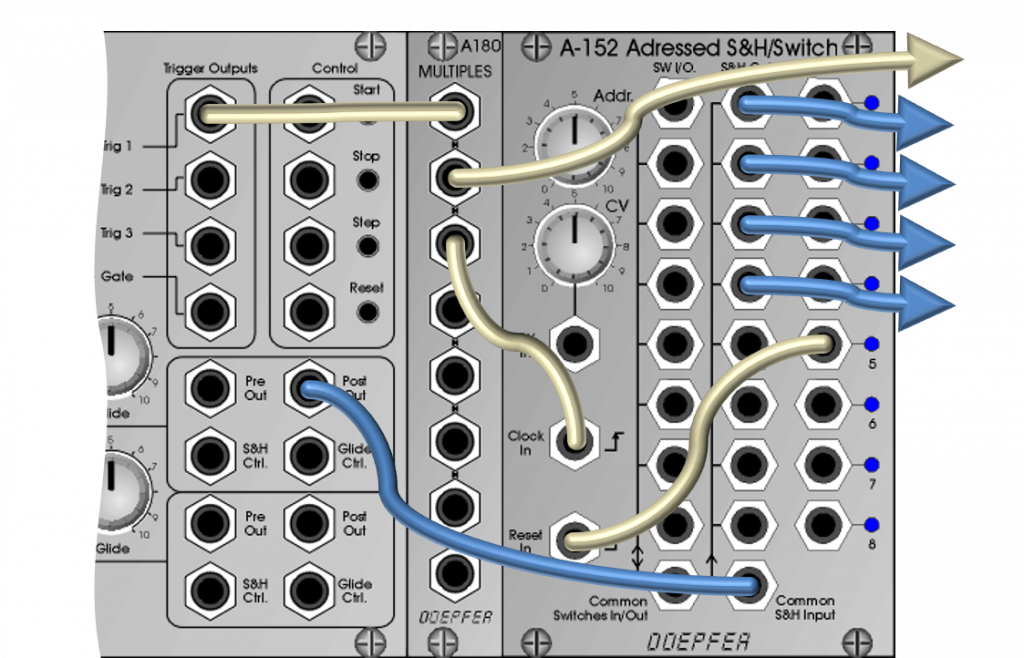
A very musical clock divider
The clock signal controls the A-152, “Dig Out 1” is used as the clock output. The division itself is determined by connecting one of the other “Dig Out” outputs to “Reset In”.
Polyphonic sequences
In addition to the switching functions already presented, the A-152 Voltage Addressed Track & Hold / Switch module can also be used as a complex Track & Hold module. The special feature is that there is not just a single T&H output as with the A-148, but 8 of them.
If you set and quantize a sequence from an A-155 in such a way that few dissonances arise even when the tones are heard simultaneously, you can distribute this sequence “in sections” to several VCOs (here in example 4). A VCO plays one note of the sequence (“track” phase) at a time until it switches to the next.
Then it continues to play and the first VCO holds the last note played (“Hold” phase).
Optionally, you can derive a longer gate signal for switching the A-152 forward by choosing a suitable frequency divider for the sequencer’s clock signal. Then e.g. 2-3 tones are played by the same VCO before switching to the next step. The length of the trigger signal and “pause” can be adjusted with an A-162 Dual Trigger Delay.
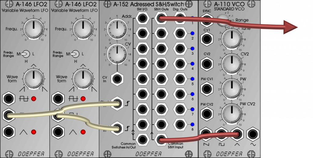
A switch used as a bucket brigade device
Module A-152 is (among other things) a Track & Hold device. The difference to a sample & hold is that although a single voltage is held (“hold”), the input signal is let through 1:1 in between.
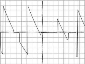
The A-152 has 8 individual T&H outputs, which can be activated one after the other via CV or trigger (and then output the input signal). Outputs that are not active constantly output the last recorded voltage. With a sufficiently high trigger speed, these constant voltages also become an interesting source of noise, which then alternates with the input signal in very rapid succession.
We start with a very high reset frequency from the right LFO, which is slowly reduced manually. The frequency of the VCO remains constant. Admittedly, this example is not particularly “musical”, but you don’t always need “pure beautiful sound” either…
Modulation of a self-oscillating filter
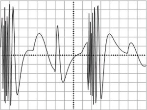
Alternatively, you can also use the output signal to modulate a self-oscillating filter – this is interesting with a slower trigger speed, since longer constant voltages of the T&H (as a sine wave with constant pitch) also become “audible” in the self-oscillating filter.
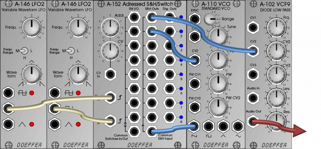
In the following sound example, the outputs of the A-152 are only used as control voltages. Primarily to modulate the self-oscillating A-102 filter, but also to affect the frequency of the VCO. The special resonance characteristics of the A-102 filter contribute to the unconventional sound.
Usage for VCO control voltages
Since, in contrast to purely mechanical switches such as the A-182-2, programmable control electronics are used here, there is theoretically a risk of damage to the module in the event of small “patch errors”, for example when two outputs are connected to one another. For this reason, protective resistors are built into each switch to prevent the module from short-circuiting.
However, when using the module to control the pitch of VCOs (e.g. to switch between sequencer and keyboard), this leads to audible voltage losses. To compensate for this, one of the buffered multiples (A-180-3 or A-180-4) or another buffer amplifier (A-185-1 or A-185-2) must be used between the A-152 and the VCO (a deployment BEFORE the A-152 does not improve).
Technical specifications
| Width | 16 HP |
| Depth | 45 mm |
| Power requirements | 40 mA (+12V) / -20 mA (-12V) |