I often used my A-111-5 as a “stopgap” when I quickly needed another simple synthesizer voice and maybe was just too lazy to patch extra VCO, VCF, VCA, ADSR and LFOs for such a secondary voice . I was often plagued by the “guilty conscience of the modularist” when I ignored the far-reaching possibilities of this extremely sophisticated module and only set a “plain vanilla” sound (which I, non-subtle mind, still liked quite a bit).
At some point at the end of 2019, the A-111-6 came onto the market: A greatly simplified mini synthesizer without LFOs, with an envelope curve that was very reduced to two parameters, in the new “Slim Line” design with smaller buttons and one from 24 TE to only 10 HP reduced width. Well, what do you expect, it will finally be the “plain vanilla” machine that you can use for very banal sounds without a guilty conscience because it can’t do any more anyway. Or yes, as we shall see.
User interface
Inputs:
System bus: As with the A-110-1 or A-111-1, the pitch of the A-111-6 can be controlled via a voltage on the system bus. The system bus can be addressed with an A-185-1 or A-185-2 or, if necessary, deactivated with a jumper on the circuit board.
As with all VCOs with CV control via the bus, you should deactivate this option if you are not using it: Otherwise, the open lines could work as “antennas” and pick up interference signals.
- 1V/Oct: Control voltage input for the VCO, with the usual characteristic of 1V/octave.
- Mod.: Control voltage input for the modulation of the VCO. Depending on the “Dest.” switch for pulse width modulation or (exponential) frequency modulation. The “Mod.” control is the attenuator for this input.
- Gate: Gate input to trigger the envelope generator.
- CVT: Control voltage input for the modulation of the time-dependent parameters of the envelope (Attack, Decay, Release).
- VCF FM1: Control voltage input for the filter cutoff frequency, the “FM1” control is the attenuator for this input.
- CV Bal.: Control voltage input for the crossfade between VCO and suboscillator or between VCO and the signal at the “Ext. In” input.
- VCF FM 2: second control voltage input for the filter cutoff frequency, without attenuator.
- Ext. In: Audio input for an additional signal that is processed with the VCF / VCA of the module.
Outputs:
- Envelope: Output for the control voltage of the envelope generated in the module.
- Out: Audio output for the module.
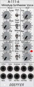
Controls:
VCO
- Tune: Fine tuning of the oscillator.
- Mod.: Attenuator for the modulation input “Mod.” (Pulse width modulation or exponential frequency modulation, depending on the “Dest.” switch.)
- PW: Manual setting of the pulse width.
- Oct.: Selector switch for the octave of the VCO over 3 octaves.
- Dest.: Switch for the modulation target: PWM (pulse width), FM (frequency modulation) or off (no modulation).
- Wave: waveform used in addition to the always present square/pulse waveform (sawtooth, triangle or off).
VCF
- Frq.: Manual controller for the cutoff frequency of the filter.
- FM1: Attenuator for the “VCF FM1” modulation input of the filter.
- Res.: Manual controller for the resonance of the filter.
VCA
- Bal.: Controller for the balance between the VCO and the sub-oscillator or between the VCO and an external audio source if this is connected to the “Ext. In” input.
- Envel. / Gate: Switch to choose between the internal envelope generator or a simple gate for controlling the VCA.
- Gain: Manual controller for the volume of the VCA, regardless of whether an envelope or a gate signal is present (continuous tone).
Env.
- Att.: Attack controller for the envelope.
- AD / ADSR / AR: Switch for the operating mode of the envelope: AD – Attack and immediately afterwards Decay (without holding phase), ADSR – attack and decay as before, then a holding phase with 50% sustain level until the end of the gate signal, then a release phase that is just as long as the decay phase, AR – Attack and then holding phase with 100% sustain until the end of the gate signal, then fading away in a release phase.
- D/R: Controller for the length of the decay or release phase (depending on the operating mode of the envelope).
Properties of the sub-modules
VCO
The VCO is a typical representative of the A-111 series with its triangular core and high precision when tracking over many octaves. For reasons of space, we only have a single tuning control that can tune the VCO either sensitively over +/- 1/2 octave or – much coarser – over +/- 2 octaves. For clean tuning, the “Finetuning” variant is always recommended, perhaps supplemented with an A-185-2 Precision Adder / Bus Access to expand the meager 3 octaves of the octave selector switch.
As with the A-111-5, the square/pulse oscillation is always present with the A-111-6. It can be supplemented with a triangle or a sawtooth (or nothing at all) via a switch. In order to eliminate the square-wave signal and only use a triangle or sawtooth, for example, you only have to set the pulse width to 0% (left stop) or 100% (right stop) with the “PW” controller: A pulse with 0% or 100% is no longer audible.
VCF
The filter is a modern 24dB Curtis-based filter, as we find on the A-111-5. It also reacts very precisely with 1V / octave via the “VCF FM2” input, so that with a high filter resonance you also have a sine wave oscillator that can be used very well musically when the pulse width (see above) is set to an extreme value and the switch for the additional waveform is set to “off”.
VCA and sub-oscillator
Here, Doepfer has incorporated an inconspicuous but very useful innovation compared to the older mini synthesizer: The module has a simple, mixable sub-oscillator that resonates an octave below the VCO and that can give the sound significantly more weight if necessary. Sure, you can hook up something like the A-115 to any VCO and add it with an extra mixer, but here we just have a single little knob that does it and that’s it! Very convenient.
In addition, there are a number of control options for the VCA of the module:
- Different operating modes of the envelope generator (AD / ADSR / AR).
- Simple gate control (“on/off”, like an organ).
- Manual amplification, independent of gate or envelopes (keyword drones).
- Gate control with slight “smoothing” by a slew generator (via jumpers).
- Combinations thereof.
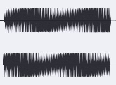
However, the “smoothing” of the gate signal is only a minimal effect. The rising flank is only very slightly rounded off and is acoustically hardly perceptible as an “attack time”. Rather hard clicks are avoided here, which the gate signal can cause when controlling the VCA in rather special settings. At the end of the gate signal, the effect is even smaller and can actually only be seen in the oscilloscope.
In the picture we see two A-111-6 with identical settings, the square is at 100% and not audible, the sawtooth of the VCO is switched on, the filter is completely open. With both mini synthesizers, the VCAs are set to “Gate” and are triggered simultaneously by an A-146 LFO. The two modules differ only in the set / unset “Slew” option. The recorded sound lasts about 0.8 seconds.
Envelope
The envelope generator is extremely reduced to two parameters (attack and decay/release) and is thus similar to the A-142-2 Dual Envelope Controlled VCA. That’s pretty minimalistic. Saves space, of course, but is it more of a hindrance? If you use several of these modules in a polyphonic context, you will very quickly be happy that you can adjust the envelopes to each other fairly quickly and precisely with only two controllers per “voice”. The switch for the operating modes quickly provides interesting variations and the CV control of the time parameters allows everything to be controlled via touch dynamics.
Configuration via the board
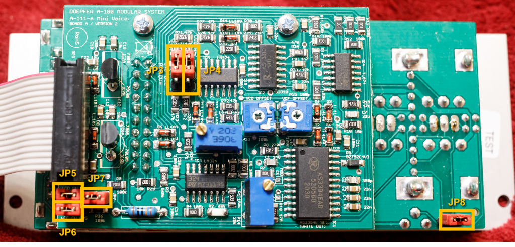
As usual with many new Doepfer modules: We have a whole range of options that we can configure using jumpers on the circuit boards.
| Jumper: | Function: |
|---|---|
| JP3 | Jumper up (in our illustration): Control voltages at the “CVT” input increase the attack time (factory setting). Jumper down: Control voltages at “CVT” shorten the attack time. |
| JP4 | Jumper up (in our illustration): Control voltages at the “CVT” input increase the decay/release time (factory setting). Jumper down: Control voltages at “CVT” shorten the decay/release time. |
| JP5 | Jumper set: connection of the control voltage for the VCO with the bus CV (factory setting). This allows the VCO to be played via a midi interface or via a bus access module without the need for a patch cable. Without this jumper, the VCO is independent of the bus CV. |
| JP6 | Jumper set: Connection of the control voltage for the filter cutoff frequency to the bus CV (factory setting). Without this jumper, the CVF is independent of the bus CV. |
| JP7 | Jumper set: Connection of the gate input to the gate line of the A-100 bus (factory setting). |
| JP8 | The jumper is located on the underlying board B. Jumper set: The range of the Tune control is approx. +/- 1/2 octave (factory setting). Without jumper: The range of the Tune control is approx. +/- 2 octaves. |
| Jumper: | Function: |
|---|---|
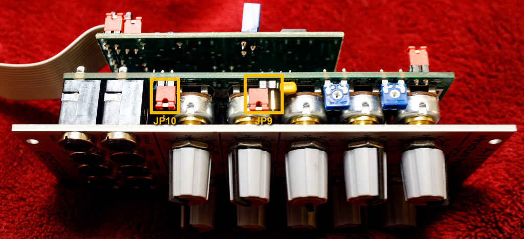
| JP9 | Jumper set: If only the external gate signal is used to control the VCA (i.e. no envelope), a slew limiter is applied to the gate. Without jumper (factory setting): No slew limiter, the gate signal controls the VCA 1:1. |
| JP10 | Jumper set: The cutoff frequency of the filter follows the control voltage at the “1V/Oct” input for the VCO (factory setting). Without jumper: The filter is decoupled from the VCO control voltage. |
Sound examples
-
A-111-3, A-111-6, A-149-4 / Random sequence
Four A-111-3 Micro Precision VCOs (sawtooth) are used as an additional sound source for four A-111-6 Miniature Synthesizers (VCO set to triangle, filter without resonance). The pitches are controlled by two A-149-4 Quad Random Sources.
The triggers for the random sources and the mini synthesizers come from an A-152 addressed T&H / switch, which is controlled with two square LFOs from an A-145-4 quad LFO (clock in and common T&H input).
I change the parameters at the two random sources (range and scales) as the process progresses. Since the cutoff-frequencies of the filters in the A-111-6 are normalized to the control voltages for the VCOs, the filter frequencies also change with higher pitches from the random generator. Some reverb and delay from the DAW.
Random sequence with four A-111-3 / A-111-6 and two A-149-4. -
A-111-3, A-111-6, A-149-4 / Random sequence with filter FM
Four A-111-3 Micro Precision VCOs (triangle) are used as modulation sources (inputs “FM1”) for the filters of four A-111-6 Miniature Synthesizers (VCO set to sawtooth). The pitches are controlled by two A-149-4 Quad Random Sources.
The triggers for the random sources and the mini synthesizers come from an A-152 addressed T&H / switch, which is controlled with two square LFOs from an A-145-4 quad LFO (clock in and common T&H input).
I start without filter FM and without resonance of the filters and change the parameters at the two random sources (range and scales) as well as (from about 1:50) the filter modulation depths, cutoff-frequencies and resonances of the filters. Since the cutoff-frequencies of the filters in the A-111-6 are normalized to the control voltages for the VCOs, the filter frequencies also change with higher pitches from the random generator. Some reverb and delay from the DAW.
Random sequence with four A-111-3 as modulation sources for the filter FM of four A-111-6 mini synthesizers. -
A-111-6 / Polyphonic setup
Although the A-111-6 is not one of Doepfer’s poly modules, I always found it obvious to use the small compact synthesizer in a polyphonic setup. You have to do without the pre-assigned connections via the circuit boards that the Poly modules offer, but you save on cabling between VCO, VCF and VCA – and that also saves a lot of space.
Four A-111-6 are controlled by an A-190-5 midi interface connected to an Arturia KeyStep Pro. Filter, VCA and envelope curves of the mini synthesizer are manually set more or less the same, only the VCOs are different: sawtooth, pulse, pulse and triangle and again pulse (with a different pulse width) are the default settings. In addition, four LFOs (triangle) from an A-145-4 modulate the pulse width. In addition to gate and pitch, the midi interface also controls the proportion of the suboscillators via the velocity.
I control the times of all four envelopes with an A-177-2 foot controller, and I modulate the four filters with an A-149-4 Quad Random Module. The random module is advanced by the trigger of the arpeggiator in the Arturia keyboard.
The four mini synthesizers are mixed with an A-138s mini stereo mixer and given some reverb and delay in the DAW.
A-111-6 in polyphonic use. -
A-111-6, A-149-4 / Mini Synth by random
In this sound example, an A-111-6 Mini Synthesizer is controlled exclusively by an A-149-4 Quad Random Generator. The four individual outputs of the Random Generator determine VCO and filter frequency, pulse width modulation, mixing with the sub-oscillator and finally the time parameters of the envelope.
The A-149-4 is triggered by a single A-146 LFO, which also triggers the envelope in the A-111-6. I manually change the voltage range of the random number generator, as well as the various parameters in the mini synthesizer. Some reverb and delay from the DAW.
The mini synthesizer controlled by random. -
A-111-6 / Sequence with modulation
For this sound example, the A-111-6 Mini Synthesizer is controlled by an A-155 / A-154 sequencer. Trigger and (quantized via an A-156) control voltage of the upper track of the sequencer are responsible for the envelope and the pitch of the A-111-6. The lower CV track simultaneously controls the mix of VCO and sub-oscillator and the length parameters of the envelope.
In addition, the pulse width of the A-111-6 is modulated by an A-118-2 Random Generator (output “RND”).
I start with an open filter, no PWM and no modulation of sub-oscillator and envelope. Then the random PW modulation and later manually the sub-octave is increased. After that, the modulation of envelope times and sub-octaves by the sequencer begins. Manual adjustments to the filter cutoff frequency, resonance, etc. follow. Some reverberation and delay from the DAW.
Sequence with the A-111-6. -
A-118-2, A-111-6 / Sample & Hold, Track & Hold
The A-118-2 controls the filter of an A-111-6 mini synthesizer. The S&H / T&H – clocking, as well as the envelope of the mini synthesizer are triggered together by an A-146 Variable Waveform LFO. Some reverb and delay from the DAW.
Sample & Hold
First we start with “Blue”, “Red”, “Rate” and “Level” at 0, then first the “Level” knob is increased to 10. After that (from about 0:30) the “Red” controller comes into play and creates significantly more dynamics in the generated S&H values (clearly negative voltages). The then also increased “Blue” controller does not change too much. “Blue” values above 8 seem to lead to a kind of internal clipping, so that only relatively constant S&H values are output. Then further manual changes to the color controls, “Level” and “Rate”, in the end everything back to 0.
Sample & Hold. Track & Hold
Same setup as before, this time the A-118-2 is set to “T&H”. Again, all sliders to 0, I start with the “Level” slider and then increase (from 0:20) the “Red” slider. In contrast to the previous sound example, I now change the pulse width of the clock LFOs until it is minimally wide at around 1:00 and the T&H reacts like an S&H. The pulse width is then increased to the maximum so that we have the “RND” signal as the modulation source throughout (approx. 1:30). Then back to medium pulse width and further manual changes, analogous to the S&H example.
Track & Hold.
Alternatives
The alternatives for the A-111-6 are manageable, but that’s not surprising. Actually there is only the A-111-5.
-
Comparison of mini synthesizers
With the A-111-5 and A-111-6, Doepfer currently has two modules in its program that – apart from the keyboard or sequencer for control – provide complete synthesizer voices without any additional peripherals. The small desktop synthesizer Dark Energy was technically almost identical to the slightly older A-111-5, but it has been out of production for a long time. The successors Dark Energy II and Dark Energy III are technically and sonically interesting, both of which were equipped with a 12dB multimode filter instead of the 24dB lowpass filter. I personally really like 12dB filters, but that’s ultimately a matter of taste. Unfortunately, Doepfer has discontinued the production of all Dark Energy synthesizers, so only the two Eurorack modules remain.
A-111-5 A-111-6 2 LFOs No dedicated LFOs 24 HP width, normal sized buttons 10 HP width, buttons in narrow “Slim Line” design Separate inputs for PWM and VCO-FM A single VCO modulation input, switchable between PWM and FM External modulation input for the VCA No external modulation input for the VCA One external modulation input for the filter Two external modulation inputs for the filter Linear filter FM possible through the VCO, additional exponential filter FM through LFO, ADSR, etc. Only exponential filter FM by envelope or external signal No sub-oscillator Sub-oscillator with its own modulation input for the balance between VCO and sub-oscillator Full ADSR envelope AD/ADSR/AR – Envelope with two parameters (switchable) Also worth mentioning is the A-109 VC Signal Processor, which has been out of production for a very long time: Of course, it lacks the VCO to play in the league of “mini synthesizers”, but it had two audio inputs, a 24dB VCF and a VCA, as well as – interesting concept – a voltage-controlled panner with stereo outputs. Very easy to use with 20 HP, but not exactly space-saving by today’s standards.
Technical specifications
| Width | 10 HP |
| Depth | 50 mm |
| Power requirements | 60 mA (+12V) / -60 mA (-12V) |