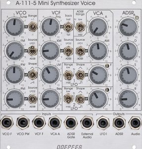
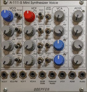
The A-111-5 is not an oscillator in the traditional sense, but a complete mini synthesizer with VCO, VCF, VCA, ADSR and two LFOs. A “Dark Energy” (first generation) for the modular system! A lot of things here are patchable, but upon closer inspection you’ll see that some signal paths are exclusively internal. For example, there is no way to tap the output of the oscillator before the filter. So the A-111-5 is not a “modular system within a modular system”.
But the A-111-5 doesn’t want to be that. It is a practical solution if you need an additional “voice” in the modular system in a very compact space, which can be used immediately and quickly without many patch cables. The only way to make this even more compact is with the A-111-6 – but with the loss of the LFOs and a simplified envelope. The A-111-5 includes a VCO, a VCF (24dB low-pass filter), a VCA, two LFOs and an ADSR generator, which can generate control voltages for volume or filter progression, for example.
In addition, the filter is unique: It allows linear frequency modulation of its cutoff-frequency and – in self-oscillation – can be played excellently tonally. The VCO’s square and pulse waves are a bit “rounded off”, but overall they are still pretty accurate (even in comparison to the A-110-1 or A-111-1).
After the A-111-5 was no longer produced due to the unavailability of CEM3394 components, Doepfer reissued the module with the AS3394.
Status: autumn 2020
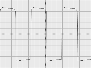
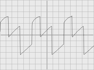
Will an external signal also be “rounded down”?
Maybe the filter doesn’t open completely and thus creates the special waveform? No, external signals are not rounded down, although they also have to pass through the filter in the A-111-5. In the figure, for example, a square wave signal from an A-110-1 VCO:
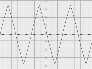
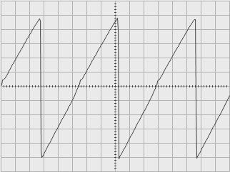
Triangle and sawtooth
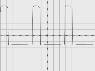
The oscillator of the A-111-5 has another special feature: the pulse oscillation is always “on”, a triangle or a sawtooth can be added using a switch. In order to get a pure triangle or a pure sawtooth, the pulse width must be set to 0% or 100% (“PW” control to the left or right end) – and thus to “inaudible”:
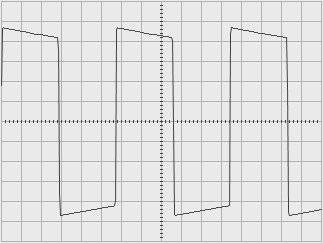
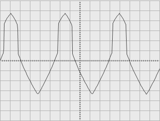
Mixture of pulse and triangle or sawtooth
With other pulse width settings you get interesting mixed sounds, which can also be achieved with any other VCO, but here they are quite simple and without additional patch cables, mixers, etc.:
User interface
Inputs:
Gate from the system bus (not shown): The ADSR generator can be triggered via a gate signal present on the system bus. If necessary, this connection can be separated internally using a jumper. Gate signals in the system bus mostly come from MIDI interfaces, but also manually from the A-164-1 Manual Gate or from any source via the A-185-1 Bus Access Module (both no longer in production).
System bus: As with the A-110-1 or A-111-1, the pitch of the A-111-5 can be controlled via a voltage on the system bus. The system bus can be addressed with an A-185-1 or A-185-2 or, if necessary, deactivated with a jumper on the circuit board.
As with all VCOs with CV control via the bus, you should deactivate this option if you are not using it: Otherwise, the open lines could work as “antennas” and pick up interference signals.
With the exception of the ADSR gate input, which interrupts the line to the gate signals of the system bus, all other inputs (audio and modulation inputs) are added in addition to the internal modulation and audio sources.
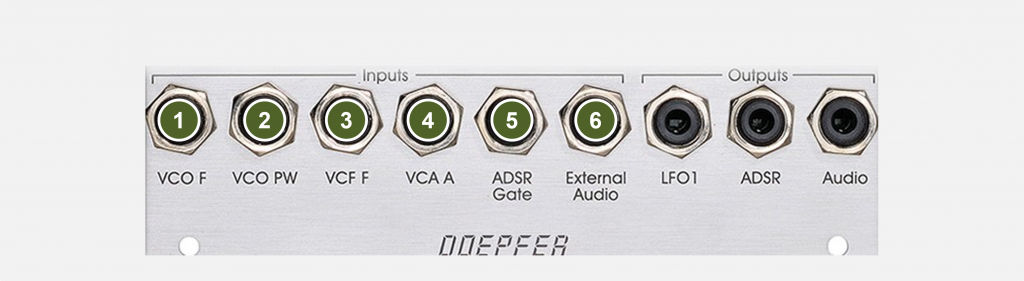
- VCO F: Control input for the frequency of the oscillator (exponential characteristic with 1 V / octave). The control voltage is added to any control voltage present on the system bus (no switching socket as with the A-110).
- VCO PW: Control input for the pulse width of the oscillator (without attenuator).
- VCF F: Control input for the cutoff-frequency of the lowpass filter (exponential characteristic with 1 V / octave – important if the filter is used in self-resonance as a second oscillator with sine wave). The input has no attenuator.
- VCA A: Control input for the amplifier amplitude (without attenuator).
- ADSR Gate: This triggers the ADSR envelope.
- External Audio: Input for feeding an external sound source (e.g. noise) into the filter and VCA.
Outputs:
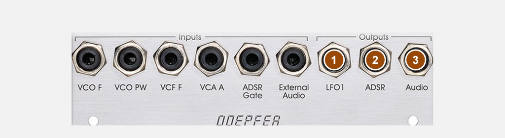
- Audio: Audio output of the overall signal after filter and amplifier.
- ADSR: ADSR generator control voltage output.
- LFO 1: Output of the control voltage of LFO 1 (compared to the internal circuit of LFO1, the voltage is inverted).
Controls:
VCO section:
- Tune: Controller for tuning the oscillator, approx. +/- 1/2 octave.
- FM: Attenuator for the frequency modulation of the VCO (1 V / octave not attenuated).
- PW: Pulse width controller. Since this controller allows to adjust everything between real 0% and 100%, you can also switch off the pulse wave with 0% or 100%.
- PM: Attenuator for the intensity of the pulse width modulation.
- Range: Switch for transposing +/- 1 octave.
- Source: Switch for the frequency modulation source: LFO1, ADSR or “off” (no modulation source).
- Shape switch to select whether a triangle, nothing (“off”) or a sawtooth is mixed in addition to the pulse (see “PW” above for switching off).
- Source: Switch for the pulse width modulation source: LFO2, ADSR or “off” (no modulation source).
VCF section:
- Frq.: Controller for setting the cutoff-frequency.
- Track: Switch to select whether the cutoff-frequency follows the frequency of the oscillator to half or full extent or not at all (“off”).
- XM: Attenuator for the exponential frequency modulation of the cutoff-frequency (V/octave).
- LM: Attenuator for the linear frequency modulation of the cutoff-frequency (V/Hz). This is quite an unusual feature for filters! This is particularly interesting when the filter becomes a sine oscillator at high resonance and is played with – the very good – tracking via a keyboard / sequencer while a linear FM is applied. The source for the linear FM is always the triangle from the VCO, regardless of whether the VCO is currently audible or whether the triangle in the VCO has been “switched on”.
- Res: Controller for the extent of the filter’s resonance, which can also be set to self-oscillation (sine oscillator).
- Source: Switch for the modulation source of the exponential frequency modulation: LFO2, ADSR or “off” (no modulation source).
VCA, LFO1 and LFO2:
Both LFOs are designed identically, so the controllers are only described once.
- Range: Switch to select whether the LFO oscillates slowly (“low”), medium-fast (“mid”) or fast (“hi”). A maximum of around 5 kHz can be achieved, which is already moderate audio range.
- Range: As above, for the second LFO.
- Source: Switch for the modulation source of the amplitude modulation: LFO1, ADSR or “off” (no modulation source).
- Shape: Switch for selecting the waveform triangle, rectangle or “off” (no voltage output).
- Shape: Same as above, for the second LFO.
- A: Controller for manual adjustment of the amplitude. Anything greater than “0” will produce a continuous tone (unless all VCO signals have been turned off or the filter has been completely closed).
- AM: Attenuator for modulating the amplitude.
- F: LFO frequency control.
- F: Same as above for the second LFO.
ADSR section:
- ADSR Range: Switch to select the speed of the ADSR generator: slow (“low”), medium (“mid”) or fast (“hi”). For reasons of compact front panel layout, this switch is located to the left of the VCA section, but has nothing to do with it.
- A: Controller to adjust the attack time until the maximum voltage is reached (while the gate signal is applied).
- D: Controller for setting the decay time between reaching the maximum voltage and the holding level that can be set using the “Sustain” controller (while the gate signal is applied).
- S: Controller for setting the holding level after the “Attack” and “Decay” phases have taken place (the level is held as long as the gate signal is present).
- R: Controller for setting the release time after the gate signal disappears (for example when a keyboard key is released again).
Possible uses
A complete mini synthesizer
The A-111-5 is an inexpensive way to get a complete synthesizer voice into the modular system. VCO and VCF often cost as much as this module, but here there are two simple LFOs, an ADSR, a VCA and a few audio or CV mixers built in. This is quite practical if you want to start with a very small modular system.
For larger and larger systems, it can be attractive to add an additional voice “just like that” that can be used quickly and without a lot of cabling, for example in live operation. And thanks to the pre-wiring and the very clever configuration of the filter, amazingly complex sounds can be achieved without much effort.
But the A-111-5 is also worth considering for entry-level modular systems: you can use the module as a starting point and then supplement it with other modules (VCO, VCF, waveshaper, etc.).
Basic setting for new sounds
As a starting point for new sounds, you can try out the following basic setting.
- VCO: Tune = 5, Range switch in the middle position, FM = 0, Source switch next to it in the middle position (“off”), PW = 0 (this means the pulse wave is switched off), Shape switch next to it on sawtooth, PM = 0, Source switch next to it in the middle position (“off”). The VCO will thus produce a sawtooth in the middle octave range.
- VCF: Frq in the upper third, Track switch to “off”, XM and LM to 0, Source switch to middle position (“off”), Res = 0. The filter will cut off some of the highs, but no other noticeable changes in the timbre.
- VCA: A = 0, AM = 10, Source switch to ADSR. The amplifier is therefore controlled exclusively by the envelope generator (ADSR).
- LFO 1 & LFO 2: Both Shape switches in the middle position (“off”). The LFOs are now switched off; the other LFO controls have no effect when “off”.
- ADSR: ADSR range switch to “mid”, A = 0, D = 0, S = 10, R = 0. The envelope is therefore a simple organ envelope (sound is present immediately when the key is pressed and immediately falls silent again when the key is released). The output of the module is connected to the audio system, the VCO F input and ADSR gate input are controlled by a keyboard or similar.
Now we’re playing around!
What you can try now:
Move the filter’s “Frq” control by hand: the sound will become varyingly dull or brilliant.
Choose a middle cutoff-frequency and play over a larger keyboard range: the higher tones will be duller than the low ones. Now switch the filter’s “Track” switch to “half” or “full”: The cutoff-frequency is now partially (half) or completely (full) adjusted to the pitch played.
How do the sounds change as you increase the resonance of the filter? What happens to the low frequency components? Pay attention to the sound at very high resonance (self-oscillation of the filter). Try other envelopes: More Attack makes the sound slowly get louder, Release makes it fade away after the key is released. Attack = 0, Decay and Sustain both at medium values make the sound more percussive. When you press a key for a longer time, the loudness remains at the volume set with the Sustain knob.
Switch on the ADSR generator as the filter’s XM modulation source and use the “XM” control to vary the intensity of the modulation.
Turn on one or both LFOs and use them as modulation sources for VCO, VCF or VCA (or a combination thereof).
Mix in the pulse oscillation of the oscillator (with PW in the middle range). Turn off the sawtooth.
“Live” interventions desirable
The module has no less than 12 3-way switches! The large number of switching options is a nice invitation to quickly and drastically change the sound. That’s something you might not necessarily associate with a modular system, right?
Fast LFOs
The two LFOs extend a long way into the audio range: used for frequency modulation of VCO (LFO1) and/or VCF (LFO2), you get a wide range of metallic and disharmonic sounds for the “Special Effects” department.
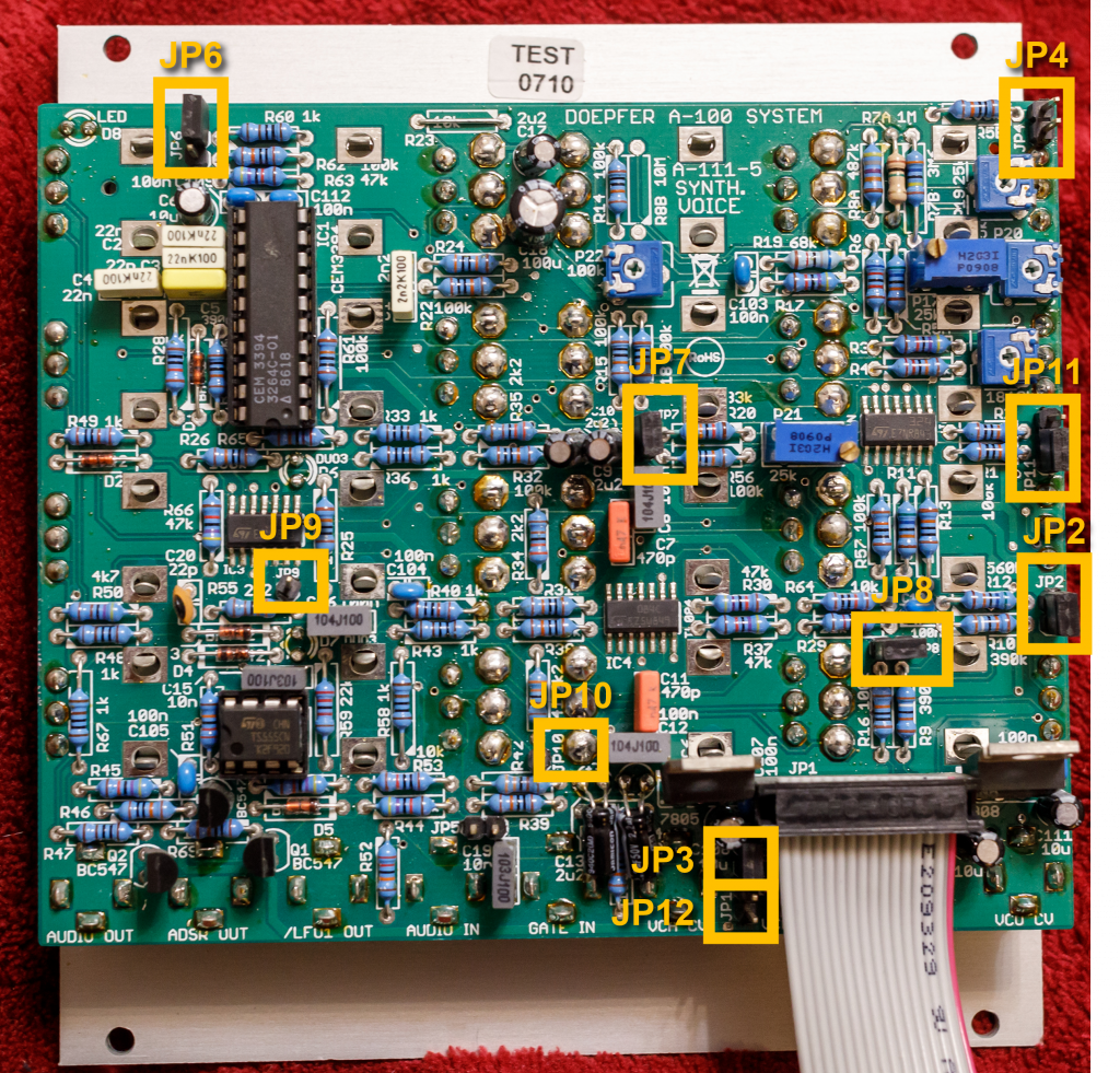
Configuration via the board
The number of jumpers for more in-depth configuration options is almost as large as the variety of controls.
| Jumper: | Function: |
|---|---|
| JP2 | Connection to the control voltage from the system bus to control the pitch of the VCO, e.g. via a Midi interface. Jumper set: connection to the CV system bus (factory setting). Jumper removed: No connection to the CV system bus. |
| JP3 | Connection to the gate signal from the system bus to control the envelope, e.g. via a MIDI interface. Jumper set: connection to the gate system bus (factory setting). Jumper removed: No connection to the gate system bus. |
| JP4 | Control range of the “Tune” knob in the VCO section. Jumper set: +/- 3 octaves. Jumper removed: +/- 1/2 octave (factory setting). |
| JP6 | Removing external input signal or internal VCO from the internal mix. Jumper set: No external signal (original modules with CEM3394) / no internal VCO signal (new edition of the module with AS3394). Jumper removed: Mixture of external signal and internal VCO with the same level (factory setting). I don’t think anyone really needs this jumper. You can easily mute both the VCO (shape switch “off” and PW control to 0) as well as the external input signal (unplug the patch cable) via the control panel. |
| JP7, JP8 | As we know, the external output of LFO1 is inverted. JP7 is the connection of LFO1 to the inverter. The upper pin of JP7 is the output of the LFO, the lower one is the input of the inverter. And the right pin of JP8 is the output of the inverter, the left is directly connected to the output socket “LFO1” on the front panel. Both jumpers are installed from the factory. If you remove both jumpers and connect (via a jumper cable) the top pin of JP7 to the left pin of JP8, then the “LFO1” output is no longer inverted. Analogously, you can either connect the single pin of JP10 (output of LFO2) directly to the left pin of JP8 (unchanged signal from LFO2 at the output “LFO1”) or you leave the jumper on JP8 and connect the JP10 pin to the lower pin of JP7 (inverted signal from LFO2 at the output “LFO1”). And finally (with JP8 plugged in) you can connect the single pin of JP9 (output of the ADSR generator) to the lower pin of JP7 to get an inverted envelope signal at the “LFO1” output. |
| JP9 | Output of the ADSR generator (only a single pin, factory setting: unused). |
| JP10 | Output from LFO2 (only a single pin, factory setting: unused). |
| JP11 | Control voltage for filter-tracking, adjustable on the front panel using a switch (off/half/full). JP11 set above: The control voltage from the system bus is used for filter-tracking. JP11 set below: The control voltage from the “VCO F” input is used for filter-tracking (factory setting). |
| JP12 | Connection of the filter to the control voltage from the system bus. Similar to the VCO, the filter, which can be controlled very precisely with 1V/oct, can also be connected to the CV bus. Jumper set: Control of the filter frequency via the system bus. Jumper removed: No control of the filter frequency via the system bus (factory setting). |
Also worth mentioning is JP5 (who can find it in the photo?), which can actually be used to connect the module’s audio output signal to the +5V line of the system bus. Very special, this bus line must of course be unoccupied. Something for “advanced hobbyists”…
Sound examples
-
A-111-5 / Filter as a second oscillator
The characteristic curve for controlling the cutoff-frequency corresponds very precisely to 1 V / octave (significantly more precise than with many other filters). Due to the two independent external control inputs for VCO and VCF, you can even play the module in two voices – here with a sequencer:
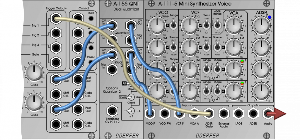
An A-155 sequencer controls both the frequency of the VCO and the frequency of the VCF in the A-111-5 mini synthesizer. The A-156 Quantizer makes it easier to set exact pitches. This setup is demonstrated in the following sound example: At the beginning you hear the pure sine of the self-oscillating filter, then the VCO comes in with a pulse wave, later modulations of the VCO and VCF follow. Towards the end, the resonance is reduced further and further until finally only the VCO can be heard.
Filter as a “second voice”. -
A-111-5 / Feedback in “External Audio”
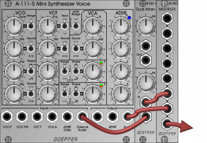
The audio output of the A-111-5 Mini Synthesizer Voice is split with the A-180-1 Multiple and fed back into its own “External Audio” input via an A-183-1 attenuator. Yes, that’s a very old trick that was often used with the Minimoog to give the already very bass-strong synthesizer a little more “oomph”. And of course this also works with the A-111-5: The “Audio” output is split up via a multiple, one part goes directly into our DAW, the other part is controlled back into the “External Audio” input of our mini synthesizer via an A-183-1 dual attenuator.
The VCO is set to sawtooth, the filter is modulated by the ADSR and operates without resonance. I start without feedback and use the attenuator to slowly increase the amount of feedback to around 8 and then back to 0. During the feedback the volume rises, but also significantly the bass spectrum and internal distortions. The VCO and envelope are controlled by an arpeggio from an Arturia KeyStep Pro. Some reverb and delay from the DAW.
Feedback. -
A-111-5 / VCO modulation in the audio sector
This sound example uses the pulse wave of the VCO in the A-111-5, PW-modulated by a moderately slow LFO2 (triangle). The filter has no resonance and is only modulated by the ADSR generator. The VCO and envelope are controlled by an arpeggio from an Arturia KeyStep Pro.
The VCO is prepared for frequency modulation by the LFO1 (“FM” control at 0), the LFO1 is set to square wave and operates in its upper frequency range “hi”. I start without modulation. Then I slowly increase the frequency modulation (“FM” control) while the frequency of the LFO is still moderate to around 5. Then I increase the frequency of the LFO to its maximum, which is very clearly in the audio range. Then frequency modulation to the maximum and at the end everything back to zero.
Some reverb and delay from the DAW.
LFO in audio range modulates the VCO. -
A-111-5 / Linear FM of the filter
A-111-5 in an “initial” setup with no modulations, no attack, decay or release, with full sustain and slightly increased basic gain “A”. The VCO generates a triangle without an additional pulse wave, the cutoff-frequency of the filter is set to the frequency of the VCO (with an octave spacing).
Both the VCA and VCF of the module are frequency controlled by an arpeggio from an Arturia KeyStep Pro, the gates for the envelope also come from there. You can hear a mixture of the VCO (triangle) and the modulated sine of the filter, which of course covers the VCO quite a bit at higher modulation intensity.
I start without filter resonance, then adjust it to maximum. You can clearly hear that the cutoff-frequency of the filter changes as the resonance increases in frequency. Almost all filters share this “fate”. Then I increase the linear frequency modulation of the filter to the maximum. We always stay in a reasonably “harmonic” sound range.
After that (from about 1:20”) I add exponential modulation of the filter frequency through the envelope (simple organ envelope without attack, decay or release). At the end I reduce all modulations back to zero. Some reverb and delay from the DAW.
Linear filter FM. -
A-111-5 / Pure” linear FM of the filter
In this sound example we only hear the filter in self-resonance, the VCO is switched off (Shape “off” and PW control to 0). An Arturia KeyStep Pro controls the pitch of the filter and VCO as well as the gate signals for the envelope.
At the beginning we hear the pure sine wave signal from the filter. As usual with the A-111-5, it has pretty clean tracking. I slowly increase the filter’s linear FM (LM control) to the maximum and back to zero. The effect is a subtle enrichment of the overtones. I had previously tuned the filter frequency and VCO as precisely as possible.
Then I drop the VCO an octave and move through the linear FM again to the maximum and back. Finally, the VCO is switched down another octave and the “LM” control is turned up again. The sound effect is now very distinctive. With the filter at maximum modulation, I now modulate the VCO with the “FM” control. The source is a very slow LFO1 set to triangle. The modulation now becomes quite “wild” and effect-alike, the melody of the arpeggio is still vaguely recognizable. At the end everything goes back until we hear the pure sine from the filter again.
Some reverb and delay from the DAW.
Filter self-oscillation with linear FM.
Alternatives
The most obvious alternative is of course the new A-111-6 – slightly slimmed down, but very sexy in the space-saving “Slim Line” design.
-
Comparison of mini synthesizers
With the A-111-5 and A-111-6, Doepfer currently has two modules in its program that – apart from the keyboard or sequencer for control – provide complete synthesizer voices without any additional peripherals. The small desktop synthesizer Dark Energy was technically almost identical to the slightly older A-111-5, but it has been out of production for a long time. The successors Dark Energy II and Dark Energy III are technically and sonically interesting, both of which were equipped with a 12dB multimode filter instead of the 24dB lowpass filter. I personally really like 12dB filters, but that’s ultimately a matter of taste. Unfortunately, Doepfer has discontinued the production of all Dark Energy synthesizers, so only the two Eurorack modules remain.
A-111-5 A-111-6 2 LFOs No dedicated LFOs 24 HP width, normal sized buttons 10 HP width, buttons in narrow “Slim Line” design Separate inputs for PWM and VCO-FM A single VCO modulation input, switchable between PWM and FM External modulation input for the VCA No external modulation input for the VCA One external modulation input for the filter Two external modulation inputs for the filter Linear filter FM possible through the VCO, additional exponential filter FM through LFO, ADSR, etc. Only exponential filter FM by envelope or external signal No sub-oscillator Sub-oscillator with its own modulation input for the balance between VCO and sub-oscillator Full ADSR envelope AD/ADSR/AR – Envelope with two parameters (switchable) Also worth mentioning is the A-109 VC Signal Processor, which has been out of production for a very long time: Of course, it lacks the VCO to play in the league of “mini synthesizers”, but it had two audio inputs, a 24dB VCF and a VCA, as well as – interesting concept – a voltage-controlled panner with stereo outputs. Very easy to use with 20 HP, but not exactly space-saving by today’s standards.
Technical specifications
| Width | 24 HP |
| Depth | 40 mm |
| Power requirements | 80 mA (+12V) / -50 mA (-12V) |