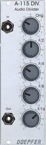
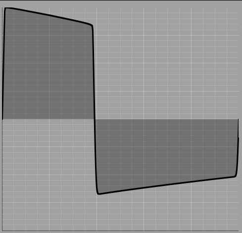
The A-115 audio divider is a simple frequency divider that outputs square wave signals of 1/2, 1/4, 1/8 and 1/16 the frequency of the input signal. This corresponds to a tone 1, 2, 3 and 4 octaves below the input signal.
User interface
Inputs:
- In: Audio input for a square wave signal. The pulse width has no influence on the output signals.
Outputs:
- Out: Audio output for a mix of original and sub-octaves.
Controls:
- Orig Controller: Portion of the original signal at the audio output.
- Controllers F/2 to F/16: proportion of the 4 sub-octaves (square-wave signals) at the audio output.
Suboscillator
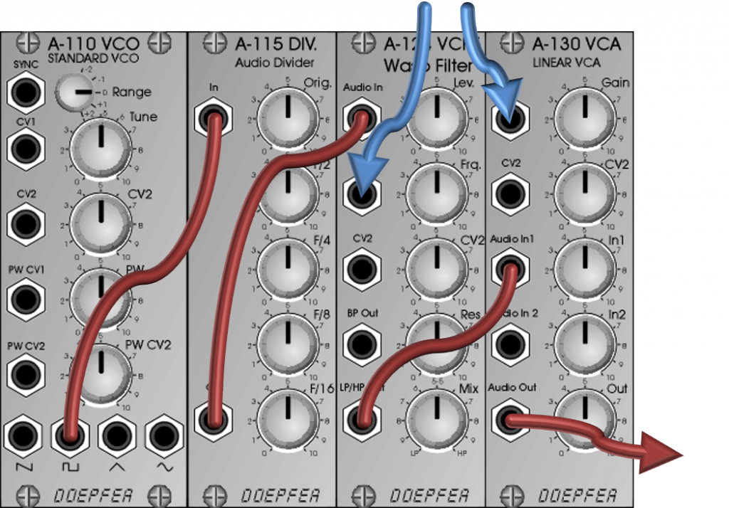
The A-115 Audio Divider can be used very well as a “sub-oscillator” to complement a VCO. Ideally, it is controlled by the square-wave signal of the VCO. Its output signal can then be fed into the further audio path, e.g. into a filter on a “standard” synthesizer voice.
Configuration via the board
Used for LFOs or as a clock divider
With its mix controls for the divided frequencies, the A-115 is predestined to be used as a sub-oscillator in the audio area. It is factory-optimized for this as an “audio divider”. The output is AC coupled.
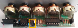
Nevertheless, it may be interesting to split modulation signals like from an LFO with square output and thus generate a regularly stepped modulation signal. For this, however, the output should be set up to output the resulting DC voltages (which is rather undesirable with audio signals). For such a DC voltage coupling, jumper JP2 must be set (plugged in) on the circuit board.
This means that the module can in principle also be used as a clock divider, but the mixing controls only make very limited sense: You will only ever turn one control up fully while all the others are at 0.
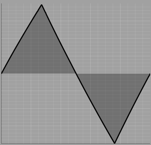
What is the “original signal”?
Before the divided frequencies are generated, a square-wave signal with the original frequency is derived internally in the module. Depending on the input signal, this can differ significantly from the original audio material.
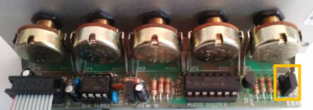
From the production of 2008 there is another jumper on the board, with which one can determine whether the original input signal should be mixed with the common output signal with the “Orig” control, or whether it should be this derived signal instead. For this, the jumper JP3 sits on a strip with 3 pins:
| Position of JP3: | Mixed signal via “Orig.”: |
|---|---|
| left 2 pins (towards the front panel) | original input signal |
| right 2 pins | derived signal |
Alternative: A-160-1
The “Clock Divider” module A-160-1 offers a very similar functionality. The Clock Divider is actually more intended for gate/trigger than for audio and therefore does not have a mixer like the A-115 module, but rather individual outputs for the divided signals. Nevertheless, it also works with audio signals and is only half as wide at 4 HP. This is worth considering for smaller systems where you only need a frequency divider every now and then.
Both frequency dividers can have problems with older versions of the A-111-1 VCO: Due to a small technical detail (AC voltage coupling), a passive attenuator or similar must be interposed with older A-111-1 There is no need to actually attenuate the signal – only the circuitry in between is required. The problem is not with the frequency dividers, but with the (older) A-111-1.
Sound examples
-
A-115 / Filter Gate Divider
In this sound example, an A-111-5 is controlled with a sequence of an A-155 / A-154 / A-156. An A-115 Audio Divider modulates the cutoff frequency of the filter in the A-111-5 Mini Synthesizer. The A-115 receives the gates from the sequencer as input. We start without modulation and during the sound example I change the proportions of the various frequency dividers, which then affect the filter in time with the sequence. Furthermore, there are no interventions in the sequence. Some reverb and delay from the DAW.
The divider divides the gate signals of the sequence and uses them to modulate the filter.
Technical specifications
| Width | 8 HP |
| Depth | 40 mm |
| Power requirements | 20 mA (+12V) / -10 mA (-12V) |