Compared to the “Superphaser” A-101-3, the A-125 looks quite modest: Only half as many controls and – yes – 35 fewer sockets. But you don’t always need such complex options as the A-101-3 offers. Quite apart from the cost factor: You get 4 complete A-125 modules for the price of a single A-101-3. Oh yes: the A-101-3 is unfortunately no longer produced. That’s a shame with such a hammer module, but maybe the incredibly versatile options were just too much for most users who were “just” looking for a phaser.
But something else makes the A-125 quite attractive: Since it is not built on a vactrol circuit, it can also implement significantly faster modulations than is possible with the vactrols in the A-101-3, which always react very slowly.
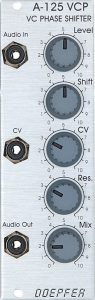
User interface
Inputs:
- Audio In: Audio input.
- CV: Control voltage input for phase shift modulation.
Outputs:
- Audio Out: Audio output for the phase-shifted audio signal (mixed with the original signal depending on the “Mix” control).
Controls:
- Level: Attenuator for the audio input.
- Shift: Manual control for the phase shift.
- CV: Attenuator for the control voltage to modulate the phase shift.
- Res.: Control for the resonance (i.e. the feedback loop) of the phaser.
- Mix: Control for the balance between the original signal and the phase-shifted signal. At control position 0 only the phase-shifted signal is output at the “Audio Out” output, at control position 10 a 50:50 mix with the original signal is output.
About Allpass Filters and “Stages”
The effect of a phaser is that an audio signal is sent through a series of allpass filters and the result is then usually mixed back with the original signal. Allpass filters are peculiar devices: they don’t by themselves filter frequencies out of the material (hence the name ALL-PASS filters), they produce inverted signals. However, they do not do this like a normal inverter, which simply inverts all voltages from positive to negative and vice versa, but the inversion happens depending on the frequency: only certain frequencies are inverted, the rest remains as it is. That’s why allpass filters have a control for the cutoff-frequency, which is called “shift” in our phaser.
Can you hear that? On its own, such an allpass filter works quite subtly. If you change the cutoff frequency of the all-pass filter, you’ll notice that it sounds a bit strange. And in fact, manufacturers of high-quality hi-fi loudspeakers or studio monitors, for example, go to great lengths to minimize such phase shifts in multi-way loudspeakers (with separate bass/mid/treble).
The effect becomes clearly audible as soon as these partly phase-shifted signals are mixed back with the original signal. Then the inverted frequencies from the allpass filters cancel each other out with the original signals: -1 and +1 then results in 0, but only at certain frequencies. With a primitive inverter everything would be wiped out as soon as we mix its output with the original signal.
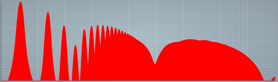
This creates a “notch” in the frequency response. In practice, any two allpass filters connected in series are capable of producing such a “notch” in the frequency response. If you look at the overtone-rich sawtooth signal of an A-110-1 oscillator in the A-125, you can see three such notches:
So our A-125 has 6 all-pass filters, or “phaser stages”. In comparison: the A-101-3 has 12 stages, but is often used as a stereo phaser with 2 x 6 stages.
Possible uses
Standard phaser
The default bet is quite simply a regular phaser: Desired audio material into the “Audio In” input, slowly set LFO with triangular signal to the “CV” socket and the “Mix” control to 10 (this corresponds to a 50:50 mix of original and shifted signal).
Unlike many other filters, the A-125 Phaser cannot be distorted with a single VCO signal (A-110 sawtooth).
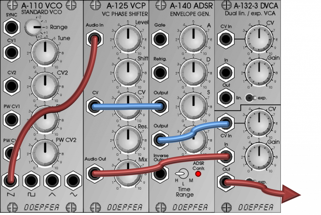
Higher frequency modulation
Try some more unusual modulation signals, e.g. ones with a higher frequency or an ADSR envelope generator. You can, for example, install the phaser in a standard signal path instead of a “normal” filter:
Alternatives
The “modular in the modular” A-101-3 is an extreme implementation of a phaser, but also costs several times as much as the A-125, requires a multiple of space in the rack and is – due to the built-in vactrols – not suitable for super-fast modulations. And unfortunately it is no longer built.
A fairly new competitor is the A-101-6 Opto FET Filter, which uses Opto FETs instead of Vactrols, which work significantly faster than Vactrols. In addition, the filter can be switched to other filter modes with jumpers. For example, for “Phasers” there are two configurations that work differently.
The A-106-6 and A-107 filters derived from the Oberheim Xpander also offer phase shifting, where the phasers are referred to as “all-pass filters”.
Sound examples
-
A-125 / Sawtooth Input
An A-110-1 provides a sawtooth signal with no further modulation as audio material for the A-125. I start with the pure phaser signal (Mix = 0) and without phaser resonance. The cutoff-frequency is modulated by an A-110-6 (sine output), I manually adjust the “LFreq” upwards from a very slow middle position. Then I also manually increase the “XTune” control of the A-110-6 from 0 to 10 and then everything back again. Since the sound samples here are more of a “technical” nature, I refrain from using additional effects from the DAW.
You can clearly hear that the effect of the modulation is very moderate at first and slowly becomes clearer as the frequency of the modulation signal from the A-110-6 increases. In addition, you can notice a very clear crosstalk of the modulation signal as soon as it enters the audio range.
Res. = 0, Mix = 0. Then I increase the phaser resonance to 5, all other settings as before. The effect becomes clearer due to the feedback, but also the crosstalk of the modulation oscillator in the audio range.
Res. = 5, Mix = 0. The next sound example is a subtle, classic phaser: “Res.” is 0 again, but the original signal (“Mix” control) is set to 5. In fact, the effect of the added original signal is very similar, for example with Res. = 5. The effect becomes clearer, the audible influence of the modulation signal may start a little later than in the previous example.
Res. = 0, Mix = 5. Now both the resonance and the mix with the original signal are set to maximum. The effect is of course very clear here, the modulation signal only makes itself felt relatively late in the sound.
Res. = 10, Mix = 10. -
A-125 / Sequence with the A-111-5
An A-111-5 mini synthesizer is controlled by an A-155 / A-154 / A-156 sequencer. The audio output of the mini synthesizer is connected to the input of the A-125 phaser. The phaser is modulated by the sample & hold output of an A-118-2 random generator. The clock of the S&H is twice as fast as the clock of the sequencer (doubling the clock signal from the A-154 via an A-160-5 ratcheting controller). Some reverb and delay from the DAW.
In the first 13 seconds we don’t hear a signal from the A-111-5, the sequencer is still stopped. During this time, I increase the phaser’s voltage control and we hear a rhythmic noise produced solely by the phaser’s modulation (no input signal).
Then the sequencer starts and we first hear the pure phaser signal without resonance (Mix = 0, Res. = 0). The effect of the phaser is initially very inconspicuous, it sounds more like slight fluctuations in pitch than “phaser”.
From about 0:40” I manually blend in the original signal using the “Mix” control, up to a maximum of 50:50.
From about 1:20” I manually increase the resonance using the “Res.” control, now the phaser gets a very clear “filter” characteristic.
Sequence with the A-111-5 as source material for the phaser.
Technical specifications
| Width | 8 HP |
| Depth | 65 mm |
| Power requirements | 20 mA (+12V) / -10 mA (-12V) |