The vocoder modules are no longer manufactured.
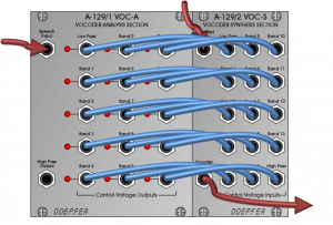
The Doepfer vocoder consists – sorry, consisted – of several modules. The two basic modules A-129/1 (analysis unit) and A-129/2 (synthesis unit or filter) were only available together.
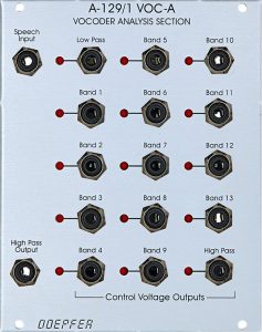
In the A-129 / 1 Analysis Section, the audio input signal is routed in parallel through 13 (steep) bandpass filters, a high- and a low-pass filter, each followed by a so-called envelope follower: the envelope followers determine the relative volume of the frequency bands isolated in this way. Each envelope follower has its own output for the generated control voltage. This is comparable to the corresponding functionality in the A-119 External Input – just separately for each frequency band.
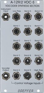
These 15 control voltages can now be used to control its counterpart, the A-129/2 Synthesis Section. Here we’ve installed the same filters again, but this time with an input for a control voltage that controls the amplitude of the output for each filter. This allows us to provide a second, completely different audio signal with the sonic “fingerprint” of the input signal from the A-129/1.
User interface
Inputs A-129 / 1 Analysis Section:
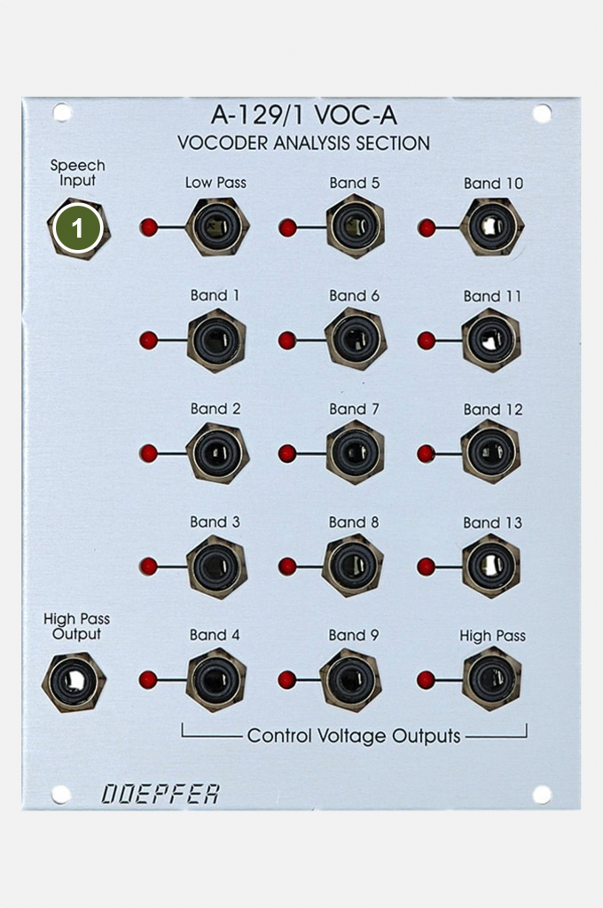
- Speech Input: Audio input for the modulator signal whose frequency response is to be impressed on the carrier signal. “Classically” the modulator signal is speech and the carrier signal is a synthesizer.
Outputs A-129 / 1 Analysis Section:
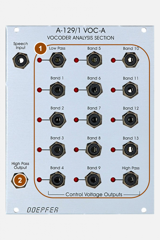
- Control Voltage Outputs (for 15 filters): Control voltage outputs for the analyzed frequency bands. If the frequency of a band is particularly pronounced (loud) in the analyzed modulator signal, then the voltage is correspondingly high. The frequencies of the filters are: 100 Hz (LP), 120 Hz, 160 Hz, 230 Hz, 330 Hz, 500 Hz, 750 Hz, 1.1 kHz, 1.3 kHz, 1.6 kHz, 2.3 kHz, 3.3 kHz, 5 kHz, 7.5 kHz and 10kHz (HP).
- High Pass Output: The signal from “Speech Input” is output at this output after it has passed the high pass filter (i.e. only the components above about 10 kHz). Sometimes it can help speech intelligibility to mix this signal with the vocoder signal.
Inputs A-129 / 2 Synthesis Section:
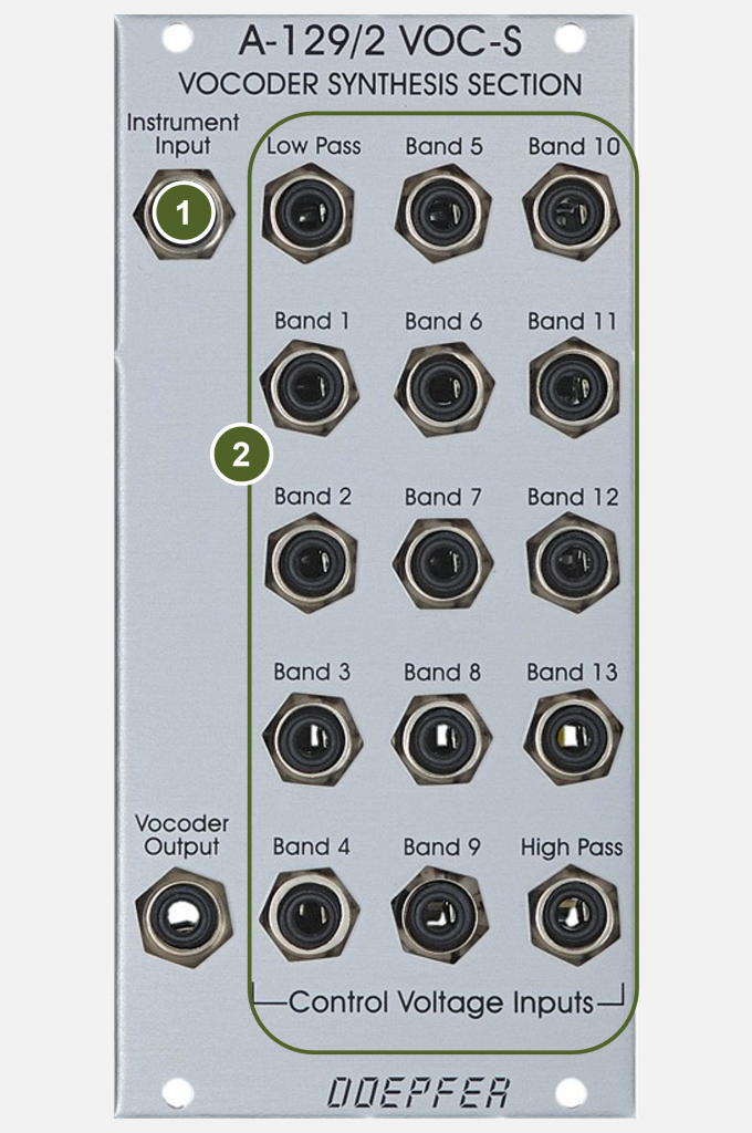
- Instrument Input: Audio input for the carrier signal to which the sound characteristics of the modulator signal are to be applied.
- Control Voltage Inputs (for 15 filters): the counterpart to the Analysis Section’s 15 control voltage outputs. The 15 filters of the module can be controlled via these control voltage inputs and significant frequency bands of the modulator signal can be transferred to the carrier signal. The frequencies of the filters are the same as in the Analysis Section.
Outputs A-129 / 2 Synthesis Section:
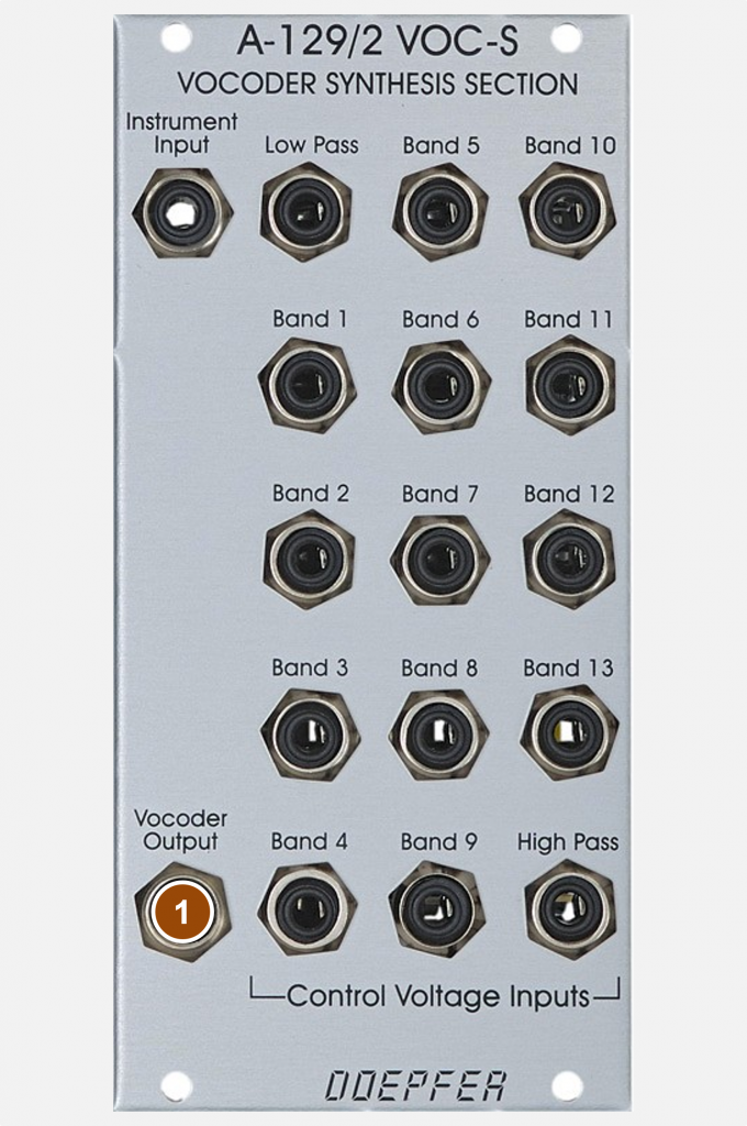
- Vocoder Output: Audio output for the filtered carrier signal from the “Instrument Input”.
Fifteen Voltage Controlled Bandpass Filters!
The A-129 / 2 Synthesis Section can be used very nicely as a kind of “Super-A-128” (Fixed Filter Bank): We have 15 control voltage inputs available!
Very interesting rhythmic sound sequences can also be realized in connection with a track & hold module (A-152) and, if necessary, random voltages (A-149-1 / A-149-2).
Vocoder Standards
In the most common use of a vocoder, a speech signal is broken down into its frequency bands in the Analysis Section and then applied to an organ, synthesizer or strings signal via the control voltages and filters of the Synthesis Section.
15 flexible control voltages
The analysis unit can also be used a little beyond the usual. You can use your voice, a drum loop, or other audio material to derive 15 control voltages for any modulation target: cutoff-frequencies, VCO frequencies, speed of a sequencer, modulation depth of an LFO (via a VCA), etc.
Sound examples
-
A-129/1+2 / Drums in vocoder
In this sound example I use a drum sequence from the “EZ Drummer” plugin as “Speech Input”. The analysis and synthesis units in the A-129/1+2 are connected 1:1. Carrier signal is colored noise from the A-118-1. First we hear the drums in the original, then I fade over to the output of the vocoder. Some reverb and delay from the DAW.
Drums in the vocoder.
Technical specifications
A-129 / 1
| Width | 20 HP |
| Depth | 60 mm |
| Power requirements | 180 mA (+12V) / -180 mA (-12V) |
A-129 / 2
| Width | 12 HP |
| Depth | 60 mm |
| Power requirements | 40 mA (+12V) / -20 mA (-12V) |