The module is no longer in production.
The A-101-3 phaser has two sub-units, each with 6 phase shifters (stages): The input signal runs through the 6 phase shifters connected in series and at the output, the original and the shifted signal can be mixed as desired using a “Mix” control.
The output of the 6th phase shifter is tapped for another purpose: It can be mixed back into the input of the first phase shifter as feedback (also inverted with the built-in polarizer). In addition, each phase shifter has a separate input (“Feedback In”) and a separate output (“Stage Out”), so that almost any phaser circuit can be implemented.
The signal path is: Audio In → Stage 1 → Stage 2 → Stage 3 → Stage 4 → Stage 5 → Stage 6 → Output mixer (original vs. phase-shifted).
After stage 6 there is another branch for the feedback loop of the phaser: stage 6 → polarizer → back to stage 1 as feedback.
The second sub-unit (right side of the module) is basically identical, but the input for the audio signal is connected to the output of the 6th phase shifter on the left sub-unit. This default connection can be interrupted by means of a switching socket.
The same applies to the control voltage: The CV input, which modulates the phase shift of stages 1 to 6, is also connected to the CV input for stages 7 to 12. This connection can also be interrupted by means of a switching socket.
And then there is an individual output for each stage and individual inputs for feedback loops – gigantic!
User interface
Inputs:
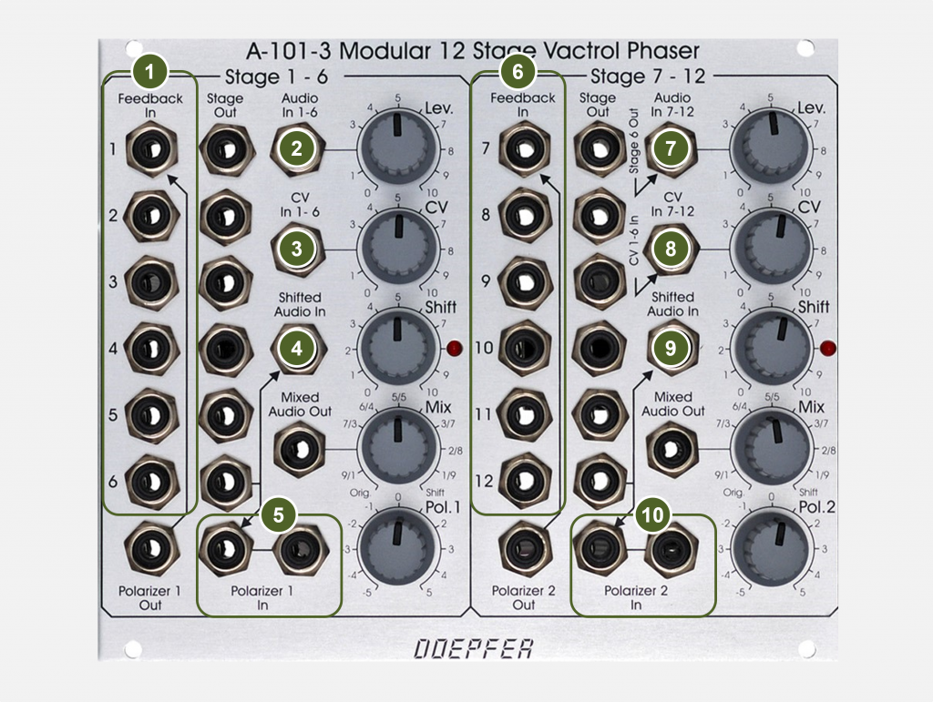
- Feedback In: Audio inputs to each stage. The feedback input of the first stage is pre-assigned to the output of the polarizer, the socket is designed as a switching socket. Each stage thus has two audio inputs: one from the phaser’s normal signal flow and one feedback input per stage.
- Audio In 1-6: Audio input for the left phaser unit. The signal then travels through the 6 stages and is fed to the output mixer and feedback loop.
- CV In 1-6: Control voltage input for modulating the phase shift of stages 1-6. The left and right sub-units of the phaser have independent modulation inputs.
- Shifted Audio In: The phase-shifted audio signal from Stage 6 is present at this input before it is mixed with the original input signal and output at the “Mixed Audio Out” socket. However, other signals can also be fed in via the switching socket.
- Polarizer 1 In (2 sockets): The phase-shifted audio signal from Stage 6 is normally present at these inputs, but it does not go to the output mixer here, but rather to the feedback loop. To the left of the “12 o’clock” position of the controller, the signal is also inverted before it is then used as a feedback signal, unless you manually patch it differently. The left input is designed as a switching socket, the signal at the right socket is mixed to it.
- Feedback In (separate for 6 Stages No. 7 to 12): See “Feedback In” for Stages 1-6.
- Audio In 7-12: See “Audio In 1-6”. However, this socket is a switching socket. Without a plug, the output signal of the phaser stage 6 (from the left sub-unit) is present here.
- CV In 7-12: See “CV In 1-6”. This socket is also a switching socket. Without a plug, the control voltage signal of the left sub-unit is present here.
- Shifted Audio In: See “Shifted Audio In” of the left sub-unit.
- Polarizer 2 In (2 sockets): See “Polarizer 1 In” of the left sub-unit.
Outputs:
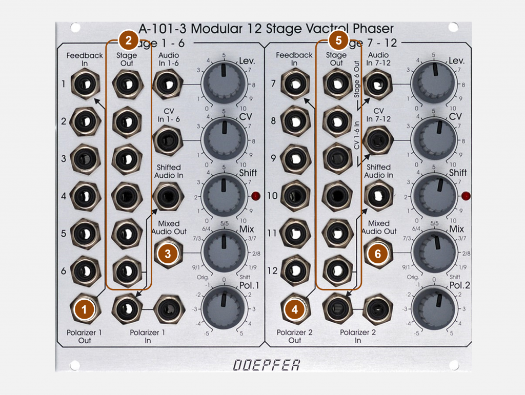
- Polarizer 1 Out: The output signal of the polarizer can be tapped at this socket. For example, you can feed the output of the polarizer of the right sub-unit (“Polarizer 2 Out”) into Stage 1 of the left sub-unit and get a real 12-stage phaser.
- Stage Out (separate for 6 stages #1 to 6): Individual audio outputs for each of the 6 phaser stages.
- Mixed Audio Out: Overall output for the left sub-unit. The “Mix” slider sets the ratio of the phase-shifted signal (from Stage 6) to the input audio signal. If the output of Stage 6 is not desired for the former (e.g. for a 4-stage phaser), then an appropriate signal can be patched into the “Shifted Audio In” socket.
- Polarizer 2 Out: See “Polarizer 1 Out” of the left sub-unit.
- Stage Out (separately for 6 Stages No. 7 to 12): See “Stage Out” for Stages 1 to 6 of the left sub-unit.
- Mixed Audio Out: See “Mixed Audio Out” of the left sub-unit.
Controls:
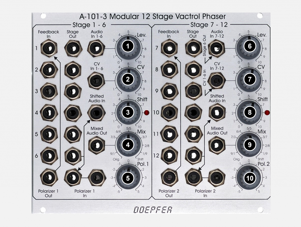
- Lev.: Attenuator for the audio input signal (socket “Audio In 1-6”).
- CV: attenuator for the control voltage (socket “CV In 1-6”).
- Shift: Manual control for the phase shift.
- Mix: This control sets the ratio of the original audio signal and the phase-shifted audio signal. For typical “phaser” sounds, the ratio is 50:50.
- Pol. 1 slider: The feedback of the phaser is controlled here – comparable to the resonance slider of a filter. Here, however, you have the advantage that this is not a simple attenuator, but the signal can also be inverted (to the left of the “12 o’clock” position of the controller). Normally the polarizer output signal is fed back into the first phaser stage – but can be freely patched if required.
- Lev. attenuator: See “Lev.” attenuator of the left sub-unit.
- CV Attenuator: See “CV” Attenuator of left sub-unit.
- Shift control: See “Shift” control of the left sub-unit.
- Mix controller: See “Mix” controller on the left sub-unit.
- Pol. 2-controller: See “Pol. 1” controller of the left sub-unit.
Possible uses
12-Stage phaser
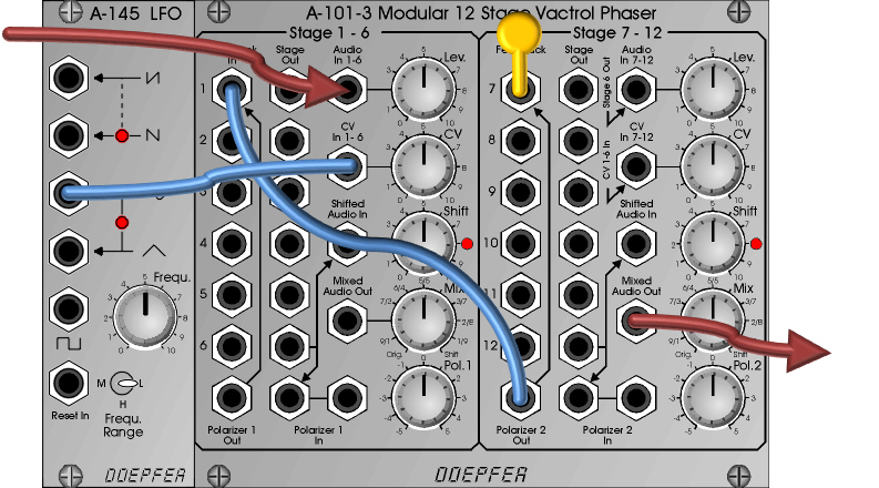
It’s actually almost a shame to use the A-101-3 as a boring “normalo” phaser, but it sounds really good: An audio signal in “Audio In 1-6” and as an output the “Mixed Audio Out” of Stage 7-12 results in a 12-stage phaser.
An LFO is connected to the CV input “1-6” for the modulation of the stages. The “Feedback In 7” socket is fitted with a dummy plug (a plug of a cable with no second end connected) so that the feedback loop from Stage 12 to Stage 7 is broken – we only want feedback from Stage 12 to Stage 1:
2×6-Stage phaser (stereo)
The audio input signal is distributed to the two inputs via a multiple. Now slightly different basic settings (“Shift” and “Pol” controls), as well as two independent LFOs as modulation sources for the modulation of the second sub-unit and then spread the two posts wide in the stereo image:

“Sound Research”
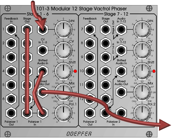
It gets exciting when you use the numerous inputs and outputs. “1-Stage-Phaser”: To replace the standard path from the 6th stage with the 1st, the first socket “Stage Out” is connected to “Polarizer In”.
The feedback path from the polarizer output already leads to the 1st stage. Now the output of the 1st stage is connected to the “Shifted Audio In” input jack for the original / effects mixer of the output section. This works well with the help of the “Polarizer 1 In” socket.
Here is a series of oscilloscope images of the output signals of different phaser configurations, each with a sawtooth signal from an A-110-1 VCO as input:


Sound examples
-
A-101-3 / Stereo mix of the stages
Three A-110-1 VCOs (sawtooth, one VCO is detuned an octave down) are mixed and amplified with an A-132-3 controlled by an A-140 ADSR. The output signal is split with a multiple and fed to both the Stage 1-6 input and the Stage 7-12 input of the A-101-3. VCO frequency and ADSR are controlled by an A-155 sequencer. Stage 1-6 shifting is modulated by the triangular signal of an A-143-3, stage 7-12 by another A-143-3. The LFO frequencies are changed manually during recording.
The outputs of shifting stages 5, 6, 9 and 12 are fed into an A-138m 4×4 matrix mixer. The four outputs of the Matrix Mixer (all in Bipolar mode) are fed back into Shifting Stage Inputs 1, 6, 7 and 12. This allows me to create feedbacks and inverted feedbacks, feed-forwards and inverted feed-forwards in quite complex ways. The two sum outputs of the phaser are then simply the left and right audio channels with a 50:50 ratio of original/shifted signal. Since the resonance of Vactrol-controlled devices can be comparatively loud, some compression and limiting (DAW) was added at the end.
Sequence with stereo mixing of the stages.
Technical specifications
| Width | 30 HP |
| Depth | 65 mm |
| Power requirements | 50 mA (+12V) / -50 mA (-12V) |