The Opto FET filter uses optical field effect transistors.
That’s a statement you have to let sink in first. Maybe meditate on it too, it certainly won’t do any harm. Until then, very quietly, the question arises as to what on earth an optical field effect transistor could be and why you need something like that for a filter.
First of all, what is a “completely normal” transistor? This is an electrical component that can regulate a larger electrical current with a small control current. This means, for example, that amplifiers can be built in which the signal to be amplified is the control current, which then regulates the larger current in such a way that it ends up being (quite simply) an amplified version of the weak control current.
A field effect transistor is a transistor in which little or almost no (control) current flows, but only the voltage is used for control. And the “optical” means that a light-sensitive unit is used here to control the transistor. In principle, you can use it to build “roughly similar” circuits as with vactrols (light-sensitive resistors), but they react much faster than the sluggish vactrols. As a reminder: We know vactrols from the A-101-2 Low Pass Gate or the A-101-1 Steiner-Parker filter. So we are dealing with somewhat exotic components that promise interesting musical results due to their slightly different characteristics from the rest of the electronics universe.
User interface
Inputs:
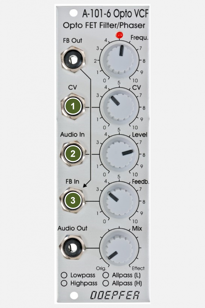
- CV: Control voltage input for the filter cutoff-frequency (or the phase shift for the allpass filter).
- Audio In: Input for the audio signal.
- FB In: Input for the filter’s feedback loop (switching jack). Here you can feed in a processed feedback signal, e.g. from the FB Out output via a VCA, to get a voltage-controlled resonance.
Outputs:
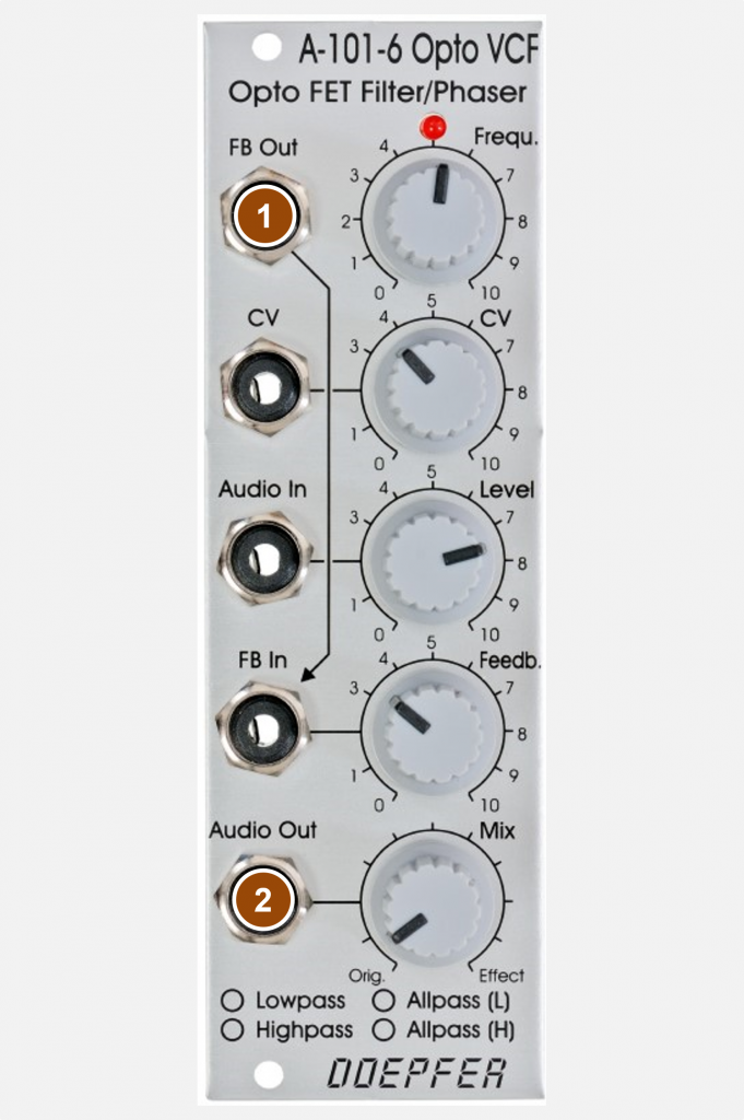
- FB Out: The feedback signal (according to the “Feedb.” control) is picked up here and can be processed further before it is fed back into the “FB In” input, for example.
- Audio Out: Audio output of the module.
Controls:
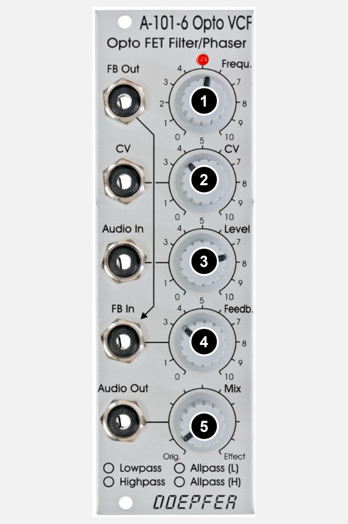
- Frequ.: Control for the filter cutoff-frequency or in the allpass configurations for the phase shift.
- CV: Attenuator for the control voltage input to the filter cutoff-frequency.
- Level: Attenuator for the audio input signal.
- Feedb.: Manual controller for the feedback of the filter.
- Mix: Crossfader for the ratio between the original signal and the filtered signal.
Possible uses
If you look at the list of previous Doepfer filters, you will quickly see that there are quite a lot of them up to now – until the introduction of the A-101-6 there were a total of 23 pieces! What should motivate a gifted tinkerer like Dieter Döpfer to build yet another filter? Why should you buy that then? In addition to the other 23 already in the rack. Not counting filters from other manufacturers.
Yes, exactly. Because it sounds very different.
But that’s only half the battle with the A-101-6. You can reconfigure the device in a fundamental way. Jumpers on the circuit board can be used to determine how the filter works in detail. Lowpass? Sure. Highpass? Anyway. Allpass (i.e. phaser)? No problem, also in two completely different variants. Details can be found in the “Configuration via the board” section.
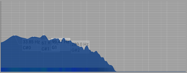
Another special feature is that the original signal and the filtered signal can be seamlessly crossfaded. The crossfader is actually intended for use of the A-101-6 as an all-pass filter, since the mix with the original signal produces sounds typical of phasers. With lowpass and highpass, you will usually stay with the 100% filtered signal, but mixing in the original signal leads to a notch filter that is sometimes quite interesting in terms of sound:

Doepfer proposes four setups for the module, in which all 6 filters are configured to the same operating mode (i.e. LP, HP or AP/L or AP/H). The series connection of 6 filter modules of 6dB each promises an extremely steep slope of a total of 36dB: Incidentally, in practice such steep filters sound much less sensational than one might think. Nevertheless, as “surgical instruments” so to speak, they have important areas of application, e.g. filtering out the internal control oscillator noise of BBDs without decimating too much of the desired sound spectrum.
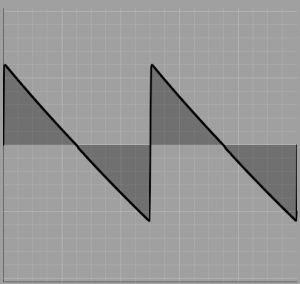
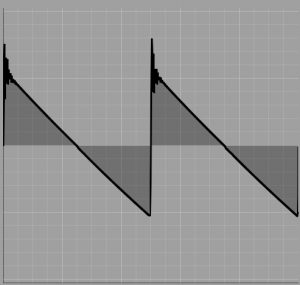
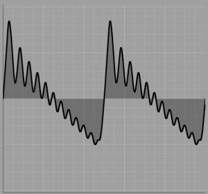
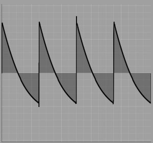
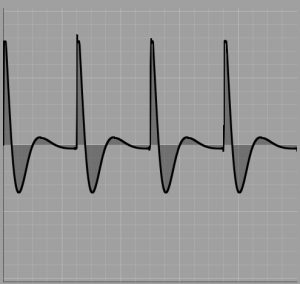
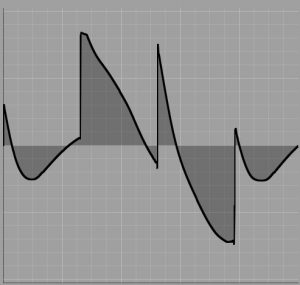
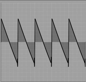
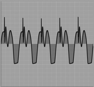
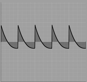
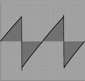
In the following we want to take a closer look at the characteristics of the filter with the oscilloscope. I chose a sawtooth from the A-111-1 as the input signal for all of the following examples:
Lowpass
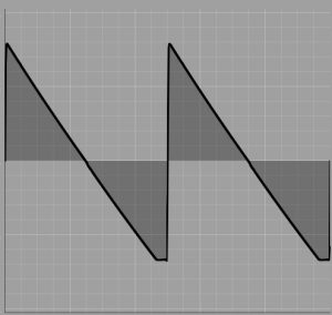
The first thing you notice – and this applies to all configurations of the A-101-6 – is that the input signal is ALWAYS inverted. So our ascending sawtooth from the A-111-1 becomes a descending sawtooth. Of course, you can’t hear that, at least as long as you don’t mix the original signal with the filtered result. (But then the original and the filtered signal cancel each other out.)
When the input is at full level (level = “10”), the filter reacts quite moderately with slight clipping in the negative part of the waveform:
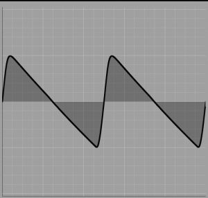
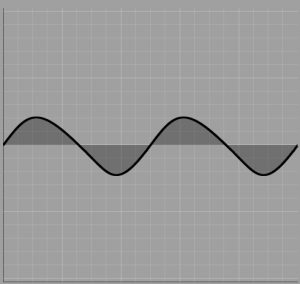
As expected, as the cutoff-frequency decreases, the signal approaches a sine wave:
As the feedback increases, additional overtones are generated:
Highpass
As a highpass filter, our A-101-6 does not work quite as neutrally as configured as a lowpass filter. The input signal is already slightly processed when the filter is completely “open” (frequency set to “0”), so the minimum cut-off frequency is comparatively high. If the filter cutoff frequency is increased further, as expected, increasingly low portions are filtered out, see the following oscilloscope image in the middle. When using feedback, harmonics are not generated as with the low-pass filter, but lower frequency ranges are emphasized (rightmost image).
Allpass “L”
One may wonder why there are two different allpass configurations. In fact, both have quite different characteristics. The allpass derived from the lowpass reacts significantly “wilder” and more chaotically with higher feedback, while the allpass derived from the highpass reacts somewhat “tamer” but breaks down completely from a certain feedback level and no longer emits an output signal.
Therefore, the allpass “L” is usually a little more productive for the display in the oscilloscope and we save a separate section for the allpass “H”. However, the differences can be heard very well in the sound samples below, especially with the “Filter sweep 50:50, feedback 10” setting.
In order to get nice examples of the maximum chaos, I set the feedback a little higher than you would normally do (see sound examples a little later).
The following is a simple pass over the frequency range with the input level set to “5”, no feedback and without the original signal being mixed in (as one would otherwise do with a “phaser”):
Bandpass
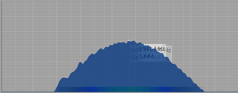
In addition to these four suggested configurations, we are of course free to choose a different configuration for each of the 6 individual filter stages. Of course, the possibility of making a bandpass filter from three lowpass and three highpass stages is particularly obvious:
Configuration via the board
Like many of the newer Doepfer modules, the A-101-6 Opto Filter can be configured via jumpers on the circuit board. Here, however, it is not just any detail like e.g.access to the control voltage of the A-100 housing bus with the A-111-3 but the basic operating mode of the filter itself! Or should we say: the basic operating mode of the FILTERS, because we are dealing with a total of 6 series-connected 6dB filters that can be individually configured as low-pass, high-pass or all-pass (in 2 variants derived from low-pass or high-pass).
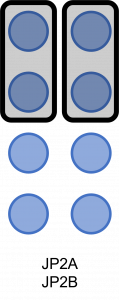
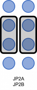
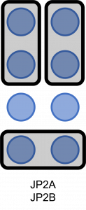
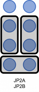
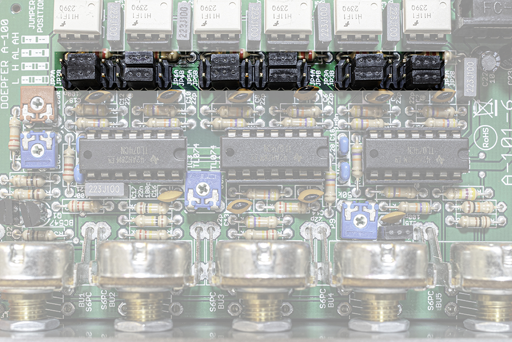
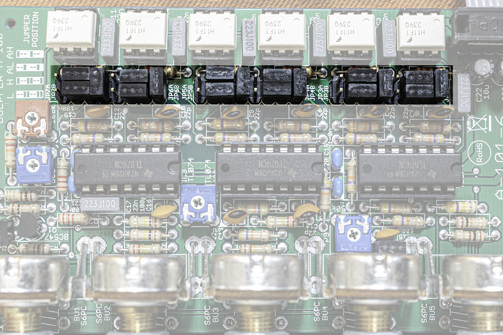
There are 6 groups of jumpers on the circuit board: JP2A/B to JP7A/B. The “A” jumpers each have 6 pins, on which 2 jumpers are always placed vertically next to each other. “Vertical” is meant here according to the labeling on the circuit board, in the board photos below the circuit boards are rotated 90° counterclockwise. These jumpers determine for each filter module whether it works in low-pass (jumpers in upper position) or in high-pass mode (jumpers in lower position). Below the 6 pins of the “A” jumpers are the 2 pins of the “B” jumpers. A jumper is only plugged in here if the filter module is to work in all-pass mode:
Lowpass
The A-101-6 filter is factory set to the lowpass configuration. The jumpers on the board are set as follows:

Highpass
For use as a highpass filter, the jumpers on the circuit board must be changed:
Allpass “L”
For the all-pass configurations, an additional jumper (perpendicular to the previous jumpers) is set for each filter level:

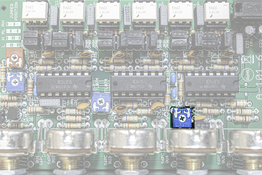
Doepfer points out that the feedback on the circuit board must be adjusted, especially after switching to all-passes. To adjust the module, you have to unscrew it from the case while the system is switched on without disconnecting it from the bus. The feedback control is set to maximum and the desired maximum feedback is adjusted using the trimming potentiometer marked below with a small screwdriver.
DO NOT REACH INTO THE HOUSING of the A-100 system! There is the transformer with life-threatening mains voltage of 230 volts!!
Allpass “H”
Without using the feedback, the “AH” configuration is not significantly different from the allpass discussed previously. The interesting effects of using feedback can be better demonstrated acoustically – see below.
Setting the jumpers on the board:
Sound examples
-
A-101-6 / Lowpass
All of the following sound samples with a sawtooth from the A-111-1, level “5” for the input signal for the A-101-6 and mix at 100% filter (without the original signal):
Filter sweep without feedback. Filter sweep as above, feedback “3”. Filter sweep as above, feedback “7”. Filter sweep as above, feedback “10”. -
A-101-6 / Highpass
All of the following sound samples with a sawtooth from the A-111-1, level “5” for the input signal for the A-101-6 and mix at 100% filter (without the original signal):
Filter sweep without feedback. Filter sweep as above, feedback “3”. Filter sweep as above, feedback “7”. Filter sweep as above, feedback “10”. -
A-101-6 / Allpass “L”
All of the following sound samples with a sawtooth from the A-111-1, level “5” for the input signal for the A-101-6 and mix at 100% filter (without the original signal):
Filter sweep without feedback. Filter sweep as above, feedback “3”. Filter sweep as above, feedback “7”. Filter sweep as above, feedback “10”. Now that we’re dealing with a phaser (which is the same as an all-pass filter), let’s hear how it sounds mixed 50:50 with the input signal:
Filter sweep with 50% filtered signal and 50% input signal, feedback “0”. Filter sweep 50:50, feedback “3”. Filter sweep 50:50, feedback “7”. Filter sweep 50:50, feedback “10”. -
A-101-6 / Allpass “H”
Again, for comparison, the filter sweeps with the A-111-1 sawtooth as the input signal for the A-101-6. First with a 100% filtered signal without the original mixed in:
Feedback “0”. Filter sweep as above, feedback “3”. Filter sweep as above, feedback “7”. Filter sweep as above, feedback “10”. As with the “Lowpass-Allpass” variant, we want to listen to the phaser-typical mixture of input signal and filtered signal:
We start again with feedback “0”. Filter sweep 50:50, feedback “3”. Filter sweep 50:50, feedback “7”. Filter sweep 50:50, feedback “10”. -
A-101-6 / Bandpass
If you configure three of the six filter stages in the A-101-6 to “lowpass” and three to “highpass” (see above for jumper settings), you get a quite powerful bandpass filter. The source material is noise from an A-118-1.
Filter sweep without feedback with a (roughly) evenly distributed noise as the input signal. -
A-101-6 / Use of the feedback loop
Here are three sound examples that are intended to convey a “musical” rather than a technical impression. All examples use the option of looping other modules into the feedback loop of the A-101-6 filter. The output signal is always a mixture of sawtooth signals from three A-110-1 VCOs, each octave apart.
The modulation is done via an A-140 ADSR and manually, gain via an A-132-3 VCA (exponential):
A-101-6 in low-pass configuration, an old A-126 frequency shifter in the feedback path. A-101-6 in high-pass configuration, a nicely distorting A-136 waveshaper in the feedback path. A-101-6 in all-pass configuration (L), an A-188-1 BBD (128 stages) in the feedback path.
Technical specifications
| Width | 8 HP |
| Depth | 65 mm |
| Power requirements | 40 mA (+12V) / -40 mA (-12V) |

