The module is no longer in production.
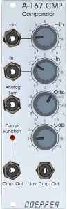
The A-167 Analog Comparator can compare voltages with each other and generate a gate signal.
There are many possibilities: comparison of two external voltages, comparison of a voltage (normal or inverted) with a positive or negative threshold value, comparison of the difference between two external voltages with a threshold value.
The module proceeds simply “mathematically”: The two input signals (each attenuated as required) are subtracted from one another and the manual offset voltage is added to the result. If the sum is greater than 0V then a positive gate signal is generated, otherwise not. Everything clear?
User interface
Inputs:
Outputs:
Controls:
An ADSR as “LFO”
The A-143-1 (Complex Envelope) module shows us how: With the help of a comparator, a new trigger can be generated from each envelope generator during the decay or release phase, which can then be used again to retrigger the envelope generator . An ADSR generator has become an LFO with a very variable waveform!
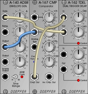
Adjusting an ADSR LFO requires a bit of finesse, but using a trigger delay to adjust the gate length is helpful. The A-167 generates a gate/trigger signal when the ADSR reaches a low voltage (release phase), but would – if used directly as a gate for the A-140 – soon switch off again, since the voltage is increased again in the attack phase. However, the A-162 Trigger Delay can generate a gate with a fixed length, which then allows the envelope to run through completely.
On the other hand – and I hadn’t considered that in the book: why not just use an LFO with a square output as a gate for the ADSR? The effort to adapt the LFO frequency to the parameters of the envelope generator is less than with the complex combination of comparator, trigger delay and ADSR. Ideally, you should use an A-146 for this, where you can also adjust the pulse width of the square-wave signal. With a conventional LFO, the comparator is useful again: you use an LFO with a triangle signal as the input for the A-167 and set the gate length on the comparator.
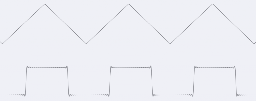
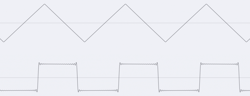
The gap controller
In principle, the gap controller ensures that the start and end of the generated square-wave signal are slightly shifted. A similar effect can be achieved with an A-170 Slew Limiter connected between the input signal and the comparator. Above we see a triangle from an A-111-1, below the rectangle derived from the A-167.
Offset generator
The module can also be used as a simple offset generator (comparable to the A-183-2): The purely internal offset voltage is available at the “Analog Sum” output; if required, an external voltage can be added (“+In” input) or subtracted (“-In” input).
The comparator as waveshaper
The comparator is “actually just” a module that can generate a gate signal by comparing two voltages.
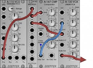
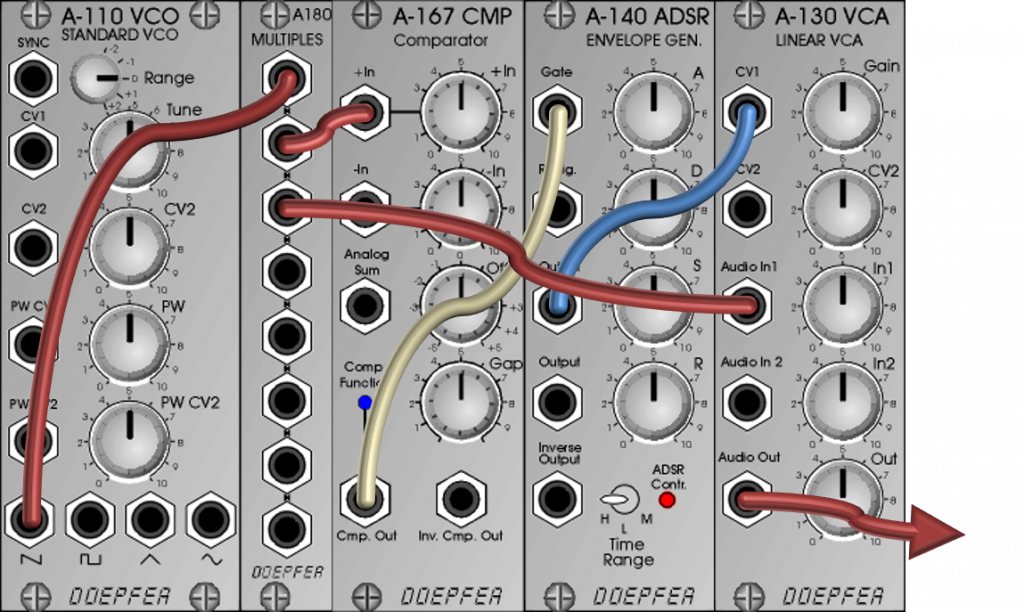
That doesn’t sound like a “sound shaper” at first. But you remember: The A-137-2 Wave Multiplier II works with comparators whose gate signal is added to the input signal. You could also multiply in the same way: For this we use an amplifier for the input signal, which is controlled via the gate signal of the comparator.
The result is reminiscent of pulse width modulation – but with a triangular signal:

That was – when I was writing the Doepfer book – a great idea. Unfortunately, it also works much more simply and without the A-167 comparator. You just have to use the VCO’s simultaneously generated square/pulse signal from the oscillator instead of the A-167. That’s it, nothing more is needed…
Two VCOs as input signals
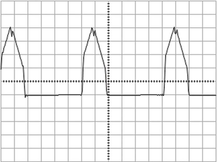
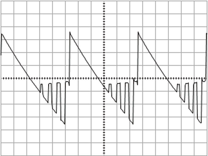
Things get a little more interesting if a second VCO (input “-In”) is connected to the patch presented above instead of the constant offset voltage. If the VCOs are slightly detuned, you get a lively spectrum rich in overtones:
Envelope instead of gate
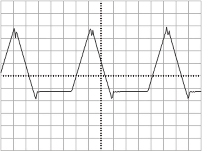
You can also use a fast envelope triggered by the gate signal of the comparator instead of the gate signal. As a result, the signal can not only be shifted in phase, but also changed:

Here, too, you can of course simply use the square wave/pulse signal of the oscillator instead of the comparator. There are only minor sound differences with triangle and sine in combination with the “Gap” control of the comparator, which can shift the generated square-wave signal slightly and then amplify other parts of the original oscillation.
Rhythmic – sound examples
A module that can generate square-wave signals is of course always a candidate for generating rhythmic structures. Here we even have the option of obtaining gate signals of different lengths.
To create semi-random rhythmic patterns, you can use two independent LFOs with triangle signals as input signals for “+In” and “-In”. Depending on the position of the two input attenuators and the offset controller, interesting patterns of square-wave signals of different lengths are created in the comparator, which are used here as a gate signal for an A-111-5.
In our example I use two triangle outputs from an A-143-3, the LFOs are set to different speeds, the input levels in the A-167 are the same. In the course of the example, I slowly turn the offset control from “-5″ up (until ca. 2’00”) and then somewhat back into the slightly negative range. Then I change the speeds of both LFOs and again to a lesser extent the offset control:
Alternatives
Since the module is no longer in production, the question of alternatives is of course particularly clear.
It’s still relatively easy when it’s just a matter of generating self-restarting envelopes. Here are a number of modules that can automatically work in a retry loop: A-141-2 VCADSR, A-142-4 Quad Decay, A-143-1 Quad AD, A-143-2 Quad ADSR or the A-171-2 VC Slew Processor. With these modules, the “loop formation” is normally much easier than with a comparator.
When used as a sound-shaping waveshaper or for rhythmic experiments, the selection is quite small. Actually there is only the new A-168-1 PWM generator, which consists of a rather puristically designed comparator with an offset that can be modulated. Additional functions such as inverters etc. would then have to be supplemented using other modules (see also the description of the A-168-1).
Technical specifications
| Width | 8 HP |
| Depth | 40 mm |
| Power requirements | 20 mA (+12V) / -10 mA (-12V) |