Pimp my VCADSR! The predecessor A-141 was a more than useful module for many purposes, but there were still “wishes” when it came to the details: The A-141 wasn’t as fast and “snappy” as the legendary A-140, and loopable envelopes like the A-143-1 or A-143-2 would sometimes be nice…
With the new A-141-2, Doepfer has packed pretty much everything that can be technically done with a single ADSR envelope:
- Voltage control – of course, we already had it with the predecessor,
- in addition, a VCA was installed, which then regulates the overall volume with voltage control,
- a common CV input that controls all three time parameters attack, decay and release,
- a range switch for particularly fast or particularly slow envelopes (drones!),
- trigger outputs that fire at the end of the attack or the release phase and can be used for an LFO application,
- In addition to the normal output, there is also an inverted output and an output that is behind the already mentioned VCA.
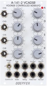
User interface
Inputs:
The module can be connected to the A-100 bus via a jumper and process the gate signals that are present there – e.g. from a midi interface.
Outputs:
Controls:
Version differences
The first version of the A-141-2 was still equipped with simple attenuators for the four control voltage inputs. The two A-141-2 in my rack are from this generation, and the sound examples were also created with them. Instead, the current modules have four bipolar controllers that positively increase the control voltages to the right of the “12 o’clock position” and invert the control voltage to the left of the middle position, up to a negative maximum when the controller is fully left.
The first version can be recognized by the labels “0 … 10” for the attenuators, the current modules are each labeled “-5 … 0 … +5”.
Basic principle of the module
The addition of a voltage-controlled envelope generator with an “onboard” VCA is somewhat reminiscent of the new A-147-2 VC LFO. In both cases, something like this is very practical, but you just need a little longer to get an overview of everything.
First of all, the A-141-2 is an ADSR envelope generator whose four parameters can be influenced via control voltages. Higher control voltages lengthen the attack, decay and release phases and increase the sustain level. With the current modules, this can be reversed using the bipolar controller, so that higher control voltages lead to a shortening of the ADR phases or a lowering of the sustain level. When used with a velocity-sensitive keyboard, you usually want to achieve shorter phases and a higher sustain level with a stronger attack (higher tension). So that’s pretty handy.
In addition to the individual control voltage inputs, there is a “Comm. CV” input that affects the duration of the three phases simultaneously. Higher control voltages shorten the phases at this input (similar to a VCLFO). There is no attenuator for this input.
As with the A-140, we find a three-stage range switch to create extremely fast or extremely slow envelopes without the control paths having uncomfortably narrow value ranges.
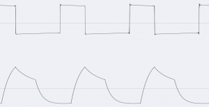
Two gate signals are generated throughout the envelope and can be used, for example, to retrigger the A-141-2, which then runs in an LFO mode: EOA and EOR.
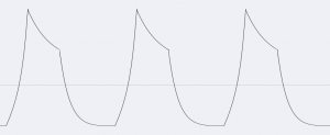
EOA starts at the end of the attack time and lasts until the original gate signal ends. If you connect the EOA output to the Retrig input, you will get a rising sawtooth LFO after the envelope has risen, as long as the gate signal is active.
EOR is started just before the end of the release phase (adjustable on the board) and lasts until the end of the next attack phase. Connecting the EOR output to the Gate input results in a cyclic attack-release envelope. Changes in decay or sustain cause only minimally different envelope curves, since the EOR gate already breaks off at the end of the attack phase and the ADSR thus immediately goes into the release phase.
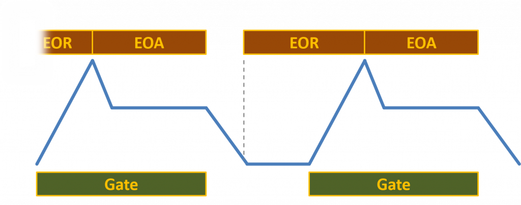
In the oscilloscope it looks like this, below we always see the actual ADSR envelope:
There are three outputs for the actual envelope. The normal output “Fixed Out” and an inverted output “Inv. Out” are standard. In addition to this, a small VCA is built into the module, through which the third output “Var. Out” is supplied. The VCA is controlled via the “Lev. CV” input.
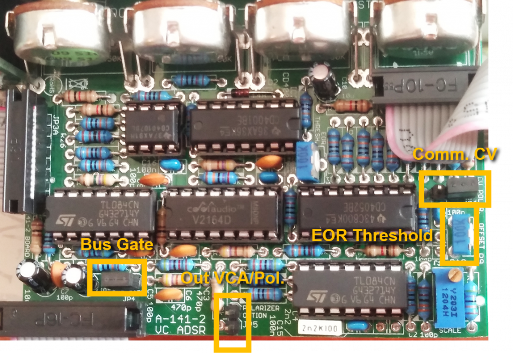
Configuration via the board
The following options can be set on the main board:
- Comm. CV: If the jumper is set to the right, the control voltage at the “Comm. CV” input reduces the attack, decay and release phases (default); in the left position, a higher control voltage lengthens these times.
- EOR Threshold: Trim pot for the threshold from which the EOR gate is started.
- Bus Gate: If the jumper is set, the module reacts to gate signals on the A-100 bus, without a jumper it does not.
- Out VCA/Pol.: If the jumper is set, the integrated VCA works as a polarizer, without a jumper as a conventional VCA (default).
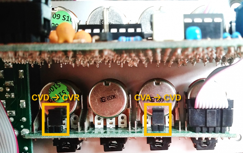
The small circuit board on the control voltage attenuators also has options:
- CVA – CVD: The control voltage input CVD is preassigned with the voltage at the input CVA.
- CVD – CVR: The control voltage input CVR is preassigned with the voltage at the input CVD.
Other curve characteristics
Doepfer points out that the characteristics of the attack, decay and release phases can be changed by feeding your own ADSR output signal into the phase control voltage inputs.
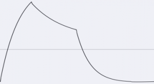
Usually the attack phase is slightly “convex”, meaning it rises steeply and then tends to flatten out, while the decay and release phases appear more “concave”, meaning they fall off quickly and then flatten out.
To change the shape of the attack phase, the inverted ADSR signal is used as the control voltage in CVA, for decay and release it is the normal shape of the ADSR signal in CVD and CVR.
Sound examples
-
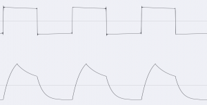
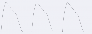
Sound example: A-141-2 / Cyclic attack envelope
If the EOA output is connected to the retrigger input, a cyclic – somewhat shortened – attack phase occurs after the attack phase has been run through once. In the example, the filter of an A-111-5 mini synthesizer is modulated by the A-141-2 envelope, both modules are simply controlled by a manual gate. With the second note, I manually change the attack time of the A-141-2. After the manual gate has ended, the release phase is initiated as usual.
Filter cutoff frequency control with repeated attack phase. -
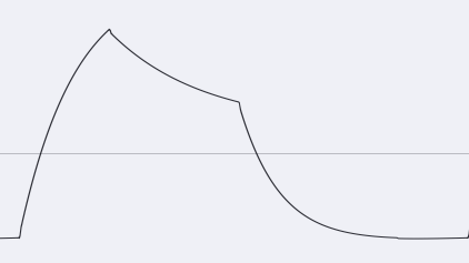
A-141-2 / The module as an oscillator
With the configuration EOR on Gate In, the A-141-2 can be used as an oscillator. Since the gate breaks off after the attack phase, a cyclic AR envelope is created in principle. The waveform can be adjusted using the attack and release controls, but the frequency is changed at the same time.
Manual changes in attack and release.
Technical specifications
| Width | 14 HP |
| Depth | 70 mm |
| Power requirements | 40 mA (+12V) / -30 mA (-12V) |