The A-150-8 is a very extensively equipped module that provides a total of 8 programmable 1:2 or 2:1 switches.
What is programmable?
- It can be programmed for each switch whether it changes its state (a) permanently after pressing the button or applying a control voltage or (b) only as long as the button is pressed or the control voltage is applied.
- The switches can be divided into groups. In this case, the switch at the top of a group is the “master” and the switches below it are “slaves”. A changeover of the “master” then immediately leads to the changeover of the underlying “slaves”.
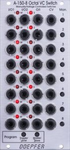
Two LEDs per switch indicate which of the two “I/O” sockets on the left is connected to the “O/I” socket on the right. So we can either switch between two input signals at the “I/O” sockets for the output at the “O/I” socket or switch between two possible outputs at the “O/I” sockets for an input signal at the “I/O” socket.
User interface
Inputs / outputs:
Controls:
Programming
To program the module, simply hold down one of the two “Program” buttons and select the desired operating mode for each switch with the respective “Man.” button.
| “Program” button: | LED display: | Function during operation: |
|---|---|---|
| Toggle / Level | “T” for toggle | After pressing the “Man.” button (or CV/trigger is applied) the connection switches and remains so even after relase of the button (or end of CV/trigger). The next pressing of the “Man.” button (or CV/Trigger) changes the switch back to its previous state. |
| “L” for level | If the “Man.” button is not pressed (control voltage below 1.5V), “I/O1” is connected to “O/I”. While the “Man.” button is pressed (control voltage above 3.5V), “I/O2” is connected to “O/I”. | |
| Master / slave | “M” for master | The switch acts as a “master”: all “slave” switches directly below it are switched together with it. The master itself is always independent of other switches. |
| “S” for slave | The switch acts as a “slave” and is always switched over together with the “master” located above it. |
By default, all 8 switches are set as “master” in “toggle” mode. Although the “slave” mode can be set for the top switch, the switch nevertheless remains independent, since there is of course no other switch above it.
Each “slave” switch can still be switched separately via its “Man.” button or a control voltage. The next time its “master” switches, it is switched over again together with it.
The same applies if different toggle and level operating modes are set for “master” and “slave” changeover switches: The slave retains its operating mode if you switch it individually, but switching via its “master” always takes place in the toggle or level operating mode of the master.
Usage for VCO control voltages
Since programmable control electronics are used here, in contrast to purely mechanical switches such as the A-182-2, there is theoretically a risk of damage to the module in the event of small “patch errors” – for example when connecting two outputs to one another. For this reason, protective resistors are built into each switch to prevent the module from short-circuiting.
However, when using the module to control the pitch of VCOs (e.g. to switch between sequencer and keyboard), this leads to audible voltage losses. To compensate, one of the buffered multiples (A-180-3 or A-180-4) or another buffer amplifier (A-185-1 or A-185-2) must be used between the A-150-8 and the VCO (usage BEFORE the A-150-8 will not bring any improvement).
Alternatives
A large number of modules offer switching functions, the simplest variant is the narrow (4 HP) A-150-1, in which it is possible to switch to the second input (or output) simply by applying a permanent voltage (gate). The A-151 cyclically switches through up to four I/O sockets with a short trigger signal, the A-152 can be switched through cyclically by trigger, but also a specific I/O socket can be selected with a control voltage. The A-155 sequencer has an input socket for each of its 8 steps, which can process both audio signals and control voltages and send them to the output. The Switched Multiple A-182-1 is not a “real” switch, but very flexible when assigning up to 6 outputs to 2 inputs, each of which uses one of the two switching strands of the (purely passive) multiple. When using with more than 2 input signals, you must ensure that the 3rd, 4th, etc. input is switched to the “off” position in order to avoid creating a short circuit. The A-182-2 is also a currentless module that offers four manually switchable 1:2 / 2:1 switches.
| Module: | Switches: | I/O: | Controlling: | Particularities: |
|---|---|---|---|---|
| A-150-1 | 2 | 1:2 or 2:1 | Gate | |
| A-150-8 | 8 | 1:2 or 2:1 | manually, Gate | Toggle, master/slave configuration of the switches |
| A-151 | 1 | 1:2 – 1:4 or 2:1 – 4:1 | Trigger (cyclic) | Reset input |
| A-152 | 1 | 1:8 or 8:1 | manually, CV, trigger (cyclic) | Direct addressing via CV, reset input, T&H, gate outputs |
| A-155 | 1 | 8:1 (not 1:8!) | Trigger (cyclic) | The module is “actually” a sequencer, reset input, extended control possible with the A-154 |
| A-182-1 | 2 | 2:6 or 6:2 | only manually | Switchable multiple with two circuit strands, currentless module |
| A-182-2 | 4 | 1:2 or 2:1 | only manually | Currentless module |
Technical specifications
| Width | 12 HP |
| Depth | 55 mm |
| Power requirements | 40 mA (+12V) / -5 mA (-12V) |