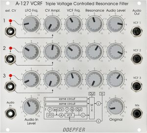
The concept of the triple resonance filter A-127 reminds me personally of the resonators in the Korg PS3100, which make this polyphonic analogue dinosaur sound so special. Technically, however, the three integrated filters in the A-127 are more comparable to the SEM filter (even if they are preconfigured differently). In terms of sound, just one of the three filters is worthwhile, especially since you can actually use all three filters separately with the optional A-127BOM breakout module.
The A-127 consists of three bandpass filters connected in parallel, the frequency of which is modulated by three built-in LFOs. Optionally, the LFOs can also be bridged via switching sockets and replaced by external modulation sources (ADSR, sequencer, etc.).
User interface
Inputs:
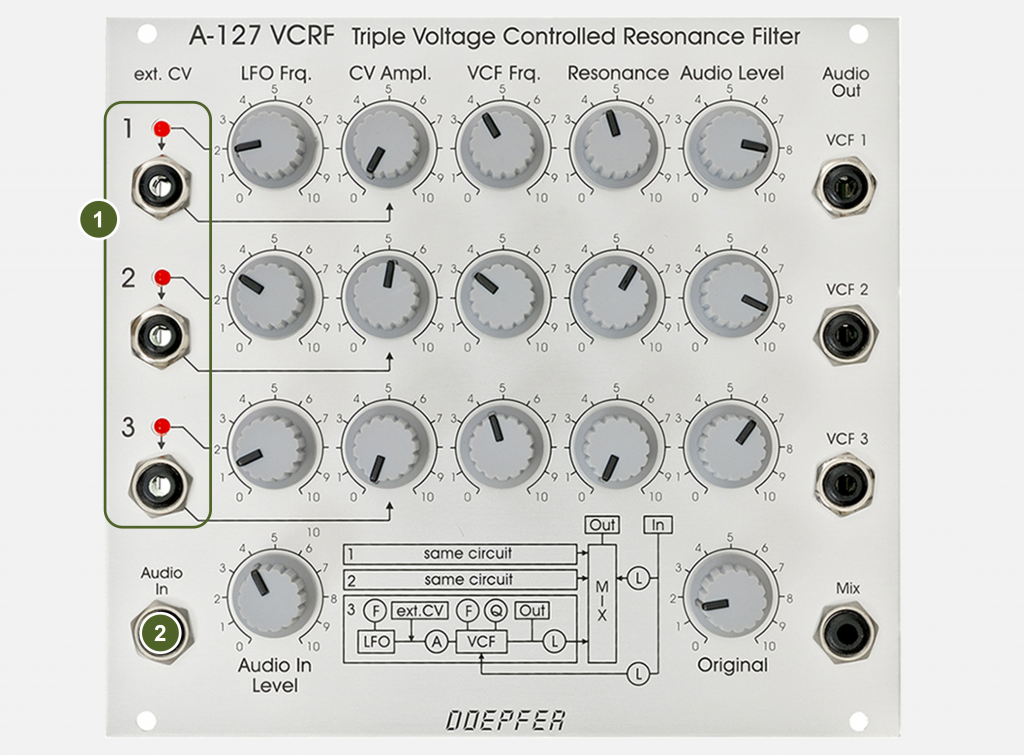
- ext. CV (Filters 1 to 3): 3 separate control voltage inputs for the modulation of the cutoff-frequencies. The inputs are designed as switching sockets so that the internal LFOs can be replaced if necessary.
- Audio In: Audio input for the filter. The audio signal is split and runs through the three resonance filters in parallel.
Outputs:
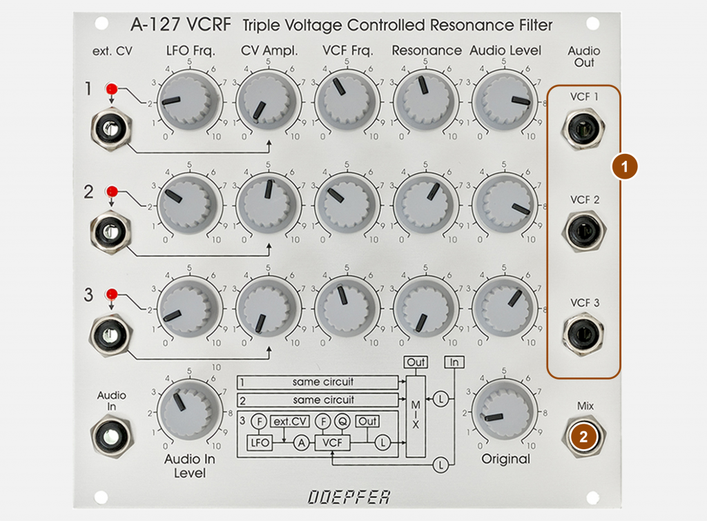
- VCF (Filters 1 to 3): Individual audio outputs for the three filters, e.g. for distribution in the stereo image.
- Mix: Audio output for the entire filter (mixing the three resonant filters with the original signal).
Controls:
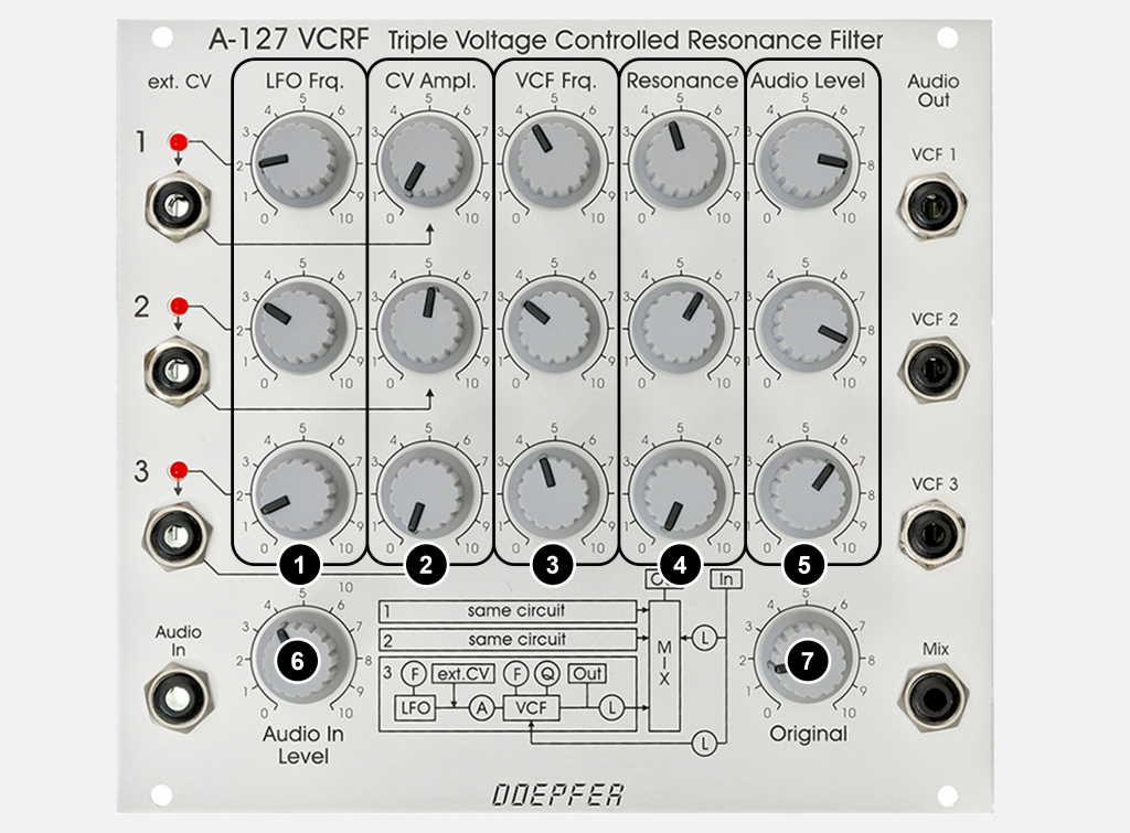
Controllers per filter unit:
- LFO Frq. (Filters 1 to 3): 3 separate controllers for the frequencies of the LFOs, which can modulate the 3 cutoff-frequencies of the filters.
- VC Ampl. (Filters 1 to 3): 3 separate controllers for the intensity (amplitude) of the modulation of the LFOs.
- FCV Frq. (Filters 1 to 3): 3 separate knobs for manual adjustment of the cutoff-frequencies.
- Resonance (Filters 1 to 3): 3 separate controllers for the resonances of the filters.
- Audio Level (Filters 1 to 3): Attenuators for mixing the shares of the individual filters in the overall sound – in the current models (since 1999) only effective on the sum output, but not on the individual outputs.
General controllers:
- Audio In Level: Attenuator for the audio input of the filter.
- Original: Attenuator for the portion of the unfiltered audio input signal at the “Mix” audio output.
Pads and drones
The filter can be used very well for pads and drones: All LFOs are set to very low – but different – frequencies, the three filters are also set differently and almost every sustained pad sound becomes an interesting and lively soundscape. If the three individual outputs are then distributed in the stereo image, very nice “widescreen sounds” can be schieved.
But high LFO frequencies can also be used for drastic sound effects (with high resonance of the filters). Here, too, the filter wins by “tripling”.
Switching to lowpass
The filters can also be switched individually as low-pass filters via jumpers on the circuit board. In the past, inventive hobbyists did this with separate switches, placed somewhere on the front panel or on a 4 HP wide blank plate. Today, the extremely luxurious breakout module A-127BOM is more likely to be used, which, in addition to bandpass and lowpass, also offers individual outputs for highpass and notch filter (bandstop) – separately for each of the three filters!
Sound examples
-
A-127 / Stereo Mix
Three A-110-1 VCOs are used with their respective sawtooth outputs and fed into the A-127 as a mix. The three individual filter outputs are mixed in an A-138m matrix mixer. I send the first and second filter to a first VCA (on the left in the stereo image) and the third and again the second filter to a second VCA (on the right in the stereo image).
First the filters in the A-127 are controlled by the internal LFOs, later I connect the outputs of an A-143-9 VC Quadrature LFO for modulations in the audio range.
Stereo mix.
Technical specifications
| Width | 28 HP |
| Depth | 55 mm |
| Power requirements | 100 mA (+12V) / -60 mA (-12V) |