The Xpander filter is based on the multimode filter design of the Oberheim Xpander synthesizer. With a total of 16 filter modes, it is not only extremely versatile, but also sounds very good throughout. If you only want a single filter for a small modular system, then give the A-106-6 serious thought.
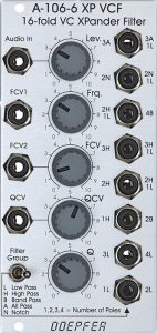
The filter has 8 individual outputs that can be switched between two groups of filter modes. Which mode is available at which output can be found in abbreviated form on the left or right of the respective output socket. “L” stands for lowpass, “H” for highpass, “B” for bandpass, “N” for notch (bandstop) and “A” for allpass (these are filters that only change the phase of the input signal and form a comb filter by mixing them with the original – this is a filter with several “comb-like” notches) – basically what phasers also do.
The slope of the filter is indicated by the number of poles: One pole leads to a frequency reduction of 6 dB / octave, so that e.g. a 2-pole filter has a slope of 12 dB, a 4-pole filter then 24 dB.
Some filter modes are also combinations of different filters, e.g. a “2H1L” filter is a 12 dB highpass filter combined with a 6 dB lowpass filter (the result is a crooked bandpass filter). The filter modes on the left (i.e. Filter Group switch to the left) are consistently incapable of self-oscillation.
User interface
Inputs:
- Audio In: Audio input.
- FCV1: Control voltage input for the cutoff-frequency (without attenuator).
- FCV2: Control voltage input for the cutoff-frequency (with attenuator).
- QCV: Control voltage input for the resonance of the filter (with attenuator).
Outputs:
- 3A / 3A1L: 3-pole allpass filter (left filter group) or the 3-pole allpass filter with 1-pole lowpass filter (right filter group).
- 2N / 2N1L: 2-pole notch filter (left filter group) or the 2-pole notch filter with 1-pole lowpass filter (right filter group).
- 2H1L / 4B: 2-pole highpass filter with 1-pole lowpass filter (left filter group) or the 4-pole bandpass filter (right filter group).
- 3H / 3H1L: 3-pole highpass filter (left filter group) or the 3-pole highpass filter with 1-pole lowpass filter (right filter group).
- 2H / 2H1L: 2-pole highpass filter (left filter group) or the 2-pole highpass filter with 1-pole lowpass filter (right filter group).
- 1H / 2B: 1-pole highpass filter (left filter group) or the 2-pole bandpass filter (right filter group).
- 3L / 4L: 3-pole lowpass filter (left filter group) or the 4-pole lowpass filter (right filter group).
- 1L / 2L: 1-pole lowpass filter (left filter group) or the 2-pole lowpass filter (right filter group).
Controls:
- Lev.: Attenuator for the audio input.
- Frq.: Controller for the cutoff-frequency, affects all filter modes.
- FCV: Attenuator for the control voltage input “FCV2”.
- QCV: Attenuator for the “QCV” control voltage input.
- Q: Filter resonance controller. Self-oscillation is only achieved with the filter modes of the right filter group.
- Filter Group Switch: To select the left or right filter group.
Possible uses
One for all
With the Xpander Filter everything in the realm of standard filter uses is possible: It sounds good in a synthesizer voice or for external audio material, it can do the usual “synth bass drums” and it’s something of a “Swiss Army knife” among filters due to its many (simultaneously usable!) filter modes.
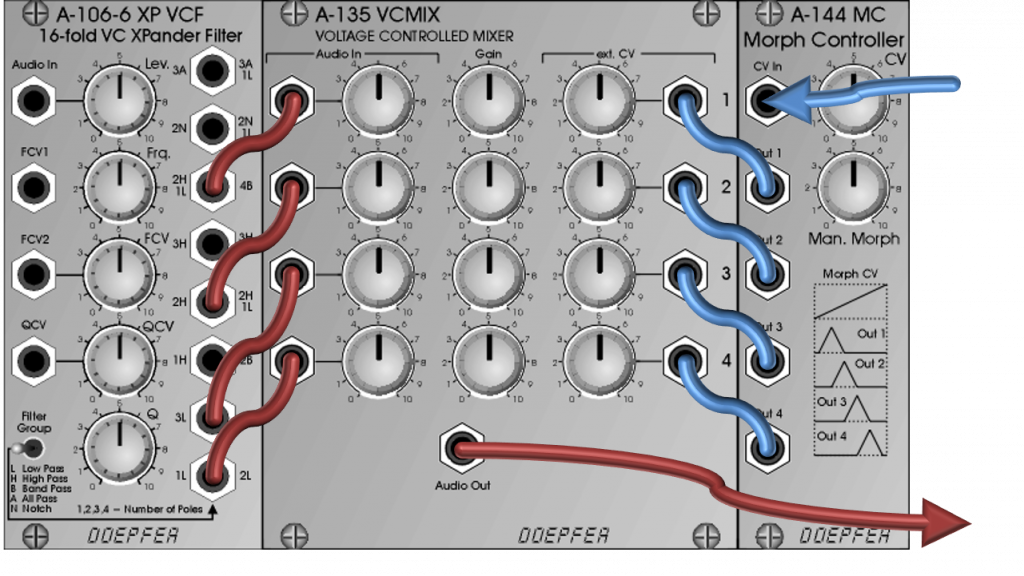
Poor man‘s A-107? (Morphing with the A-106-6)
The A-106-6 module still has something like a “big brother”: The A-107 filter, which unfortunately is no longer produced. In the (analog) core, both are very similar, but the A-107 also has storable digital electronics to control smooth morphing between different operating modes, as well as 20 additional filter modes on board. In fact, the A-106 originally came about as a stripped down version of the A-107 filter monster.
With the help of the separate outputs and a crossfader or voltage-controlled mixer with morphing controller, smooth transitions between different filter modes can also be created with the A-106-6 (or e.g. with the A-121). Since the outputs sometimes have quite different levels, the interposition of attenuators / amplifiers is worth considering (an A-107 can do all of this “on board”, but has to be programmed for each step).
Phasers
Phasers are all-pass filters that are mixed with the original signal. A “pure” all-pass filter would sound “like nothing”, the effect only becomes noticeable through the characteristic cancellation of individual frequencies when the original and filtered signal are mixed (comb filter). In the A-106-6, too, the all-pass filter is a mixture of the original signal and the filtered signal, which already has the typical sound characteristics of a phaser.
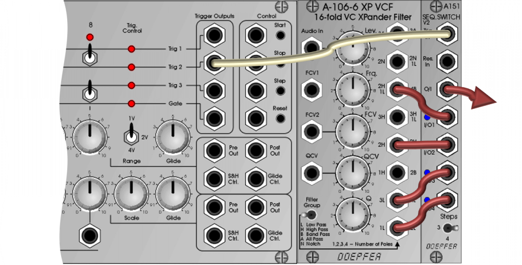
Hard switching via sequencer
Hard switching between modes can also be very attractive, e.g. if the whole thing is controlled in time by a sequencer:
Sound examples
-
A-106-6 / Switching the outputs with a sequencer
In this sound example, the 8 individual outputs of the A-106-6 are routed to the 8 inputs of an A-155 sequencer, the sequencer is used to switch between the outputs.
The sawtooth outputs of 3 A-110-1 VCOs are used as the input signal for the filter, one VCO is transposed down by 1 octave. The filter’s cutoff frequency is modulated by a slow LFO and the fast envelope of an A-140 ADSR. The filter’s resonance (referred to as “Q” here) is modulated by another A-155. Both sequencers are synchronized, but use a different number of active steps or are controlled with differently divided triggers.
First we start with the right filter group (3A/1L, 2N/1L, 4B, 3H/1L, 2H/1L, 2B, 4L, 2L), after 1 minute we switch to the left filter group (3A, 2N, 2H/1L, 3H, 2H, 1H, 3L, 1L).
Switching the outputs with a sequencer. In another sound example we use a similar setup, but this time the resonance of the filter is modulated via sample & hold and the input signal is driven into saturation in the second half of the sound example. Again we hear the right filter group (with an undistorted input signal) for one minute, the left filter group (also with an undistorted input signal) for one minute and then the same thing with a distorted input signal for one minute each:
Switching the outputs with a sequencer, S&H modulation of the resonance, saturation.
Technical specifications
| Width | 12 HP |
| Depth | 50 mm |
| Power requirements | 50 mA (+12V) / -50 mA (-12V) |