The Vactrol filter has several special features. Most striking: There is a separate input for each of the operating modes lowpass, bandpass and highpass. This allows several very different sound sources to be treated differently in a single filter. Only the cutoff-frequency and the resonance (and resonance control) are common. If that’s too much for you: The “BP” and “HP” sockets are normalized to the “LP” socket, i.e. if only one plug is plugged into the “LP”, the signal is distributed to the other two inputs.
The circuit is based on the filter of the “Synthacon” synthesizer from Steiner-Parker, which was built between 1975 and 1979. Instead of the diodes used in the original, however, so-called “vactrols” are used here.
That brings us to another special feature: vactrols. A vactrol is a photoresistor connected to a light-emitting diode in a small, light-tight capsule. The brighter the light emitted by the LED, the lower the resistance of the vactrol becomes. Vactrols can be driven very far without distortion, but they are relatively sluggish (i.e. react slowly to changing control voltages!) and do not have a clear characteristic: This makes circuits with vactrols very interesting in terms of sound, because they often sound “soft” but are also a little unpredictable in their behavior.
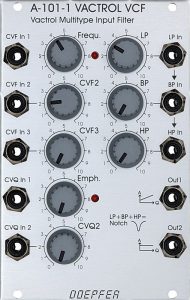
User interface
Inputs:
- CVF In 1: Control voltage input for the cutoff-frequency (without attenuator).
- CVF In 2: Control voltage input for the cutoff-frequency (with attenuator).
- CVF In 3: Control voltage input for the cutoff-frequency (with attenuator).
- CVQ In 1: Control voltage input for the resonance of the filter (without attenuator).
- CVQ In 2: Control voltage input for the resonance of the filter (with attenuator).
- LP In: Audio input for the lowpass filter.
- BP In: Audio input for the bandpass filter. If there is no plug connected to this switching socket, the input signal from “LP In” is used.
- HP In: Audio input for the highpass filter. If there is no plug connected to this switching socket, the input signal from “LP In” (or that from “BP In”) is used.
Outputs:
- Out1: audio output of the filter.
- Out2: Resonance-compensated audio output of the filter. With higher resonance/self-oscillation, the overall output level of a filter usually increases. Here the output signal is attenuated according to the controller or control voltage of the resonance.
Controls:
- Frequ.: Control for the cutoff-frequency (affects all filter modes simultaneously).
- CVF2: Attenuator for the control voltage input “CVF In 2”.
- CVF3: Attenuator for the control voltage input “CVF In 3”.
- Emph: Control for the resonance (self-oscillation) of the filter.
- CVQ2: Attenuator for the control voltage input “CVQ In 2”.
- LP: Attenuator for the “LP In” audio input.
- BP: Attenuator for the “BP In” audio input or, alternatively, for the audio component from “LP In” that is routed to the bandpass filter.
- HP: Attenuator for the “HP In” audio input or, alternatively, for the audio component from “LP In” (or from “BP In”) that is routed to the highpass filter.
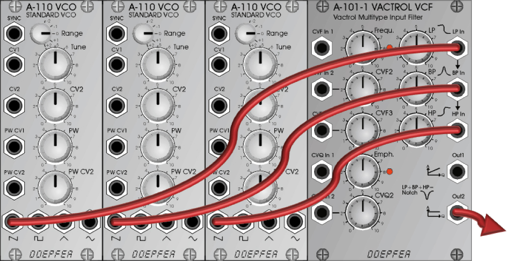
Different octaves for the input signals
Several different sound sources in the filter inputs offer unusual design options – try three oscillators on the inputs:
- “LP In” transposed up 2 octaves,
- “BP In” in medium tuning and
- “HP In” transposed 2 octaves down.
Passing through the cutoff-frequency completely now results in an extremely wide sound spectrum – particularly impressive with a slightly higher filter resonance.
Notch filter
A notch filter (i.e. notch in the frequency response) is obtained when all three input attenuators are set to the same values and only the “LP In” input is used.
The reason is that the three inputs are normalized, i.e. the input signal from “LP In” is also used in “BP In” and in “HP In”. If only one plug is plugged into “LP In” but all three input attenuators are turned up equally, a notch filter is created as a mixture of the three filter types.
Behavior in the bass range
Even with higher resonance, the filter does not react by lowering the bass components of the input material! (Use output “Out1”)
However, due to the sluggishness of the control using vactrols, the filter is not really suitable for typical “electronic bass drums” – the course of the cutoff-frequency simply does not “snap” fast enough. However, “electronic tom-toms” (the typical Simmons sound) can be implemented very nicely with the A-101-1.
Different A-101-1s will also sound different due to vactrols’ component tolerances. For example, my A-101-1 shows no distortion of the input stage (even with attenuator = 10).
Heavily distorted self-resonance
Don’t let my vactrol prose fool you: the attribute “smooth and low distortion” most certainly doesn’t apply to the filter’s self-oscillation! Shortly after the onset of self-oscillation, the sine signal begins to clip and later changes to an approximate square wave signal. In combination with the audio inputs, this results in quite wild and “evil” filter sounds that, for example, go far beyond the behavior of an A-124 Wasp filter.
Sound examples
-
A-101-1 / Sequence with crossfading of the filter inputs
Three A-110-1 VCOs are controlled and mixed by an A-155 sequencer and serve as input for the A-101-1. The filter is modulated by the VCO pitch control voltage, an A-140 ADSR and an LFO (slow triangle wave). The resonance-compensated Out 2 is used as the output.
I start with just lowpass input, fade to bandpass and then highpass. The resonance is increased manually and we can hear the filter’s rather sudden and very intense resonance. Something like that can be useful for special effects, drums, etc. A little later, the LFO frequency is increased into the audio range (around 4-5 kHz): but since the filter works with sluggish vactrols, it doesn’t follow the modulation frequency too far. Filter-FM in the audio range is therefore not possible.
Sequence with the A-101-1.
Technical specifications
| Width | 16 HP |
| Depth | 50 mm |
| Power requirements | 30 mA (+12V) / -30 mA (-12V) |