The Quad VCLFO is actually almost a “real” VCO: It even has temperature compensation, which allows it to remain in tune even with external temperature fluctuations. Doepfer points out that the A-143-4 is not quite as accurate as the VCOs of the A-110 or A-111 series, but from my point of view it can be an interesting replacement for one – no actually four – conventional VCOs in some cases.
However, a few restrictions must be observed: The oscillators (with a triangle core) only generate triangle and square waves – no sawtooth, no sine and no variable-width pulse. In addition, there is only one controller for the frequency for each oscillator, which can optionally range (by means of a jumper on the board) over approx. 1 or over approx. 5 octaves – the “real” VCOs offer a little more comfort.
User interface
Inputs:
Outputs:
Controls:
Sync options – reset and direction
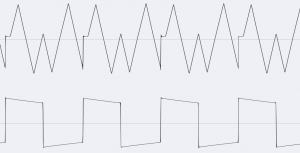
The module has comparatively complex sync options, in which the reset to 0 volts is sometimes treated separately from a subsequent change in direction of the generated waveform. Oscillators A to C only have one common input for reset and change of direction, but with oscillator D you can change the direction via the “Direction” input independently of the reset. If this input (switch socket) is not assigned, the signal from the “Reset” input is prewired internally and used.
A square wave is normally used as the sync signal for all sync inputs. The reset to 0 volts always occurs on the rising edge of this sync signal, but the direction change occurs on both the rising and falling edges of the sync signal.
In addition, oscillator D allows three different variants of direction changes via a toggle switch:
- up: The direction of the waveform always increases after the rising/falling edges of the sync signal. If the triangle was falling, it changes its direction afterwards, if it was rising, the direction of the triangle remains the same.
- down: The direction of the waveform always falls after the rising/falling edges of the sync signal. If the triangle was falling, it stays that way; if it was rising, it changes direction.
- both: The direction of the waveform is always changed after the rising/falling edges of the sync signal.
In combination with the reset (which in the case of oscillator D does not have to take place at the same time as the change of direction), you get quite complex waveforms.
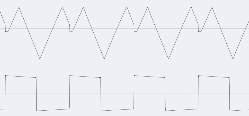
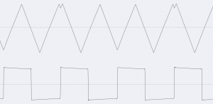
In comparison, the reset / direction behavior of Oscillator D, reset and direction are performed by the same oscillator (i.e. only the “Reset” input is used):
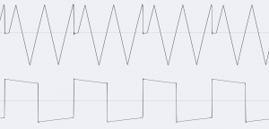
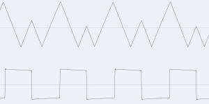
If only the “Direction” input (without “Reset”) is used on oscillator D, it looks like this:
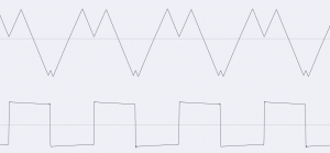
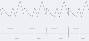
So far we have only looked at the effects on the triangle output. This is where the clearest changes in the waveform take place. But interesting effects can also be achieved with the square output:
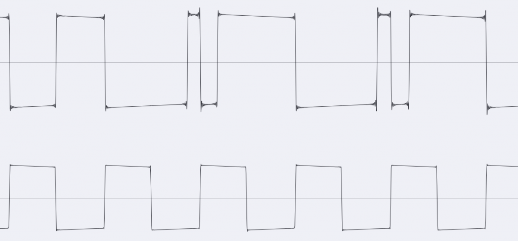
In the sound example, both the frequency of the “master” oscillator and the “slave” oscillator (with square wave) are varied:
Sound example – reset and direction independent of each other
Oscillator D (triangle output) from the A-143-4 is influenced by two other oscillators (both square) via the “Reset” and “Direction” inputs (direction “both”). The frequencies of all three oscillators are manually changed during the sound example.
“Oscillator Lock”
With the A-143-4, four oscillators were accommodated in a very small space, not only because it is a compact module, but also actually on the circuit board. This can lead to an interesting (but not always desired!) side effect: As soon as the frequencies of two oscillators get very close, they can “catch” each other and synchronize their frequencies (oscillator lock).
Sound example – master outputs and “oscillator lock”
Here the sum output for the triangular signals (on the left in the stereo image) and the sum output for the square-wave signals (on the right in the stereo image) are used at the same time. An A-143-9 VC Quadrature LFO modulates the frequencies of the A-143-4 oscillators with its four phase-shifted sine outputs, a second A-143-9 carries out the resets and changes of direction – also out of phase. Oscillator D has reset and change of direction on “both”. During the sound example, the frequencies of the two control LFOs as well as the frequencies and modulation strengths of the four oscillators of the A-143-4 are changed manually. The output sound, which always appears very “harmonious”, is clearly determined by the fact that the frequencies of the four oscillators in the A-143-4 repeatedly “lock in” to common frequencies or divider ratios.
Configuration on the board
Type of direction change and bus control voltage:
On the smaller board “BOARD A” there are four jumpers for the way the direction of the oscillators A-C is changed, as well as the connection to a control voltage on the A-100 bus, which can influence the frequency of all four oscillators.
| Jumper: | Function: |
|---|---|
| JP5 / oscillator A | left = UP (factory setting), right = DOWN, without jumper = BOTH |
| JP6 / oscillator B | left = UP (factory setting), right = DOWN, without jumper = BOTH |
| JP7 / oscillator C | left = UP (factory setting), right = DOWN, without jumper = BOTH |
| JP8 / A-100-Bus | Jumper inserted = connection to the A-100 bus, without jumper = no connection |
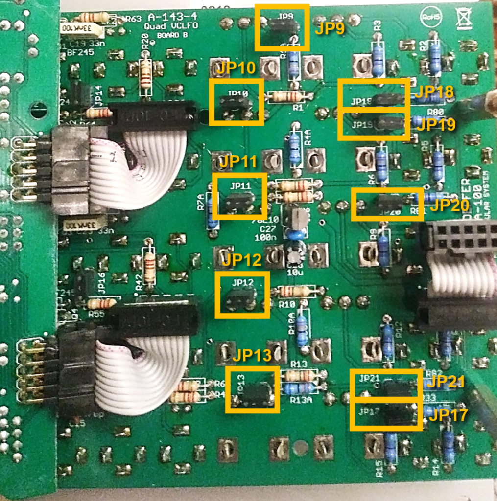
There are additional jumpers on the “BOARD B” circuit board that open up further configuration options for the oscillators:
Control range of the “Freq.” knobs:
If the following jumpers are set, the control range of the respective “Freq.” controller is +/- 5 octaves (factory setting), without jumpers it is +/- 1 octave.
| Jumper: | Concerns “Freq.” controller: |
|---|---|
| JP9 | of oscillator A |
| JP10 | of oscillator B |
| JP11 | of oscillator C |
| JP12 | of oscillator D |
| JP13 | common control for all oscillators (at the bottom) |
Super low mode:
The “Super Low Mode” is actually only a pre-assignment of the “CV In 2” sockets (switching sockets) with a negative voltage. With the “CV In 2” controls fully open at position 10, the frequency of the corresponding oscillators (or all oscillators together with the “Common” control completely ccw) is greatly reduced. Instead of the jumpers, you can also set the “CV In 2” controls to 0 or simply plug a dummy plug into the corresponding input socket. In other words, you can save yourself the hassle of removing these jumpers.
If the following jumpers are set, the corresponding oscillators work in “Super Low Mode” with a pre-assigned negative voltage on the “CV In 2” inputs (factory setting); without jumpers, this pre-assignment is omitted (see previous figure of the circuit board).
| Jumper: | Oscillator: |
|---|---|
| JP17 | all oscillators via the common “CV In 2” control |
| JP18 | oscillator A |
| JP19 | oscillator B |
| JP20 | oscillator C |
| JP21 | oscillator D |
Reset and direction:
If the following jumpers are set, reset and change of direction are carried out simultaneously for the respective oscillator (factory setting). Without a jumper, there is only a reset to 0 volts without a change in direction.
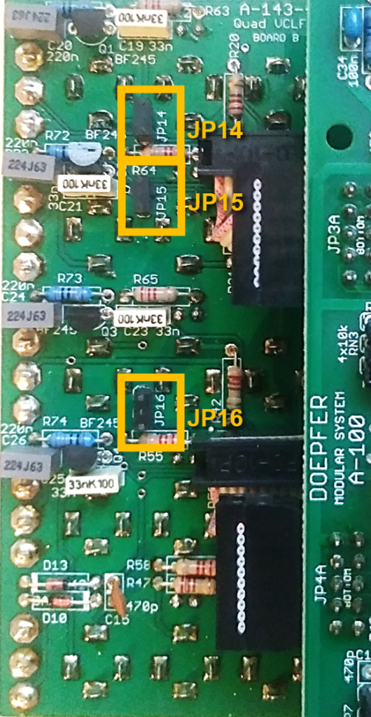
| Jumper: | Oscillator: |
|---|---|
| JP14 | oscillator A |
| JP15 | oscillator B |
| JP16 | oscillator C |
Version differences
In the first edition of the module, the switches for LFO and VCO mode were labeled incorrectly. At the top it said “low” instead of “VCO” and at the bottom it said “high” instead of “VCLFO”.
Alternatives
Alternatives for the A-143-4 are rather rare, and then with significantly different functionality. If it’s just four LFOs without voltage control and reset options, then the A-143-3 Quad LFO or its “Slim Line” brother A-145-4 Quad LFO is probably a better choice, especially since both do not have the problem (or feature!) of the oscillator lock and the A-143-3 also offers sawtooth.
The A-143-1 Complex Envelope Generator, which can be switched to an LFO, has reset options but no real voltage control.
The A-147-2 VC Delayed LFO is just a single LFO, but equipped with a wealth of options, voltage control, reset and all common waveforms.
The A-111-4 Quad Precision VCO can be used much more easily in the audio area than the A-143-4 and is also equipped with reset (sync) options.
Technical specifications
| Width | 22 HP |
| Depth | 60 mm |
| Power requirements | 100 mA (+12V) / -100 mA (-12V) |