The A-190-3 is a small midi interface that has a lot of features despite its narrow 6 HP. In comparison to the big A-190-4 you have to make a few compromises – no clock/reset outputs, no midi thru, no software LFO and no display. A supposedly “small” difference should be mentioned: With the A-190-3, 0 to +5 volts are possible for controlling the VCO pitch, with the A-190-4 it is -3 to +10 volts. That doesn’t sound like much at first, but it means a difference between a moderate 5 octaves tonal range with the A-190-3 and an almost unbelievable 13 octaves with the A-190-4!
However, the small interface has a total of four control voltage outputs instead of only two on the A-190-4 and (in my opinion) an extremely practical controller for the portamento function.
The direct predecessor of the A-190-3 interface was the A-190-2 (“Low-Cost-Midi-to-CV/Gate-Interface”), which is no longer available. Except for the USB socket as an alternative midi input, it offered almost the same functionality.
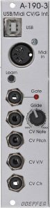
User interface
Inputs:
Outputs:
Controls:
Programming
As soon as the “Learn” button is pressed – for at least one second – the basic settings of the module can be defined via MIDI commands (see next section). During this, the LED next to the gate output will blink. As soon as a MIDI command has been sent to the module, learn mode ends and must be activated again to set further parameters. The setting made is saved in the module and is available again after switching off/on.
Which MIDI commands change what?
| Parameter: | MIDI command: | Remarks: |
|---|---|---|
| MIDI channel and reference note | A MIDI note (pressing a key) sets the channel and reference note | The reference note is the lowest accepted MIDI note. For it, 0 V is output at the CV Note output. |
| Velocity for CV V/V | OFF: PrChg #1 ON: PrChg #2 | Here it is determined whether the CV V/V output takes into account the attack dynamics (Note On Velocity) in addition to the MIDI Volume (MIDI Controller #7) or not. |
| Velocity for CV Ctr. | OFF: PrChg #3 ON: PrChg #4 | Here it is determined whether the output CV Ctr. not only takes into account an arbitrarily definable MIDI controller (default = modulation wheel / MIDI controller #1) but also the touch dynamics (note on velocity) or not. |
| Retrigger | OFF: PrChg #5 ON: PrChg #6 | When “Retrigger” is activated, the generated gate signal is briefly interrupted when a new note is played, even when playing legato, so that the envelope is restarted. |
| Polarity of the gate signals | POSITIVE: PrChg #7 INVERTED: PrChg #8 | Normally, the gate signals are output as a positive voltage when a midi note is played, and as 0 V when no note is played. This behavior can be inverted. |
| Velocity mode for CV V/V | 0-127: PrChg #11 2 values: PrChg #12 | Here it is determined whether the note on velocity is taken into account in full at the CV V/V output (128 values) or only two values with a threshold value of 100 (accent mode). |
| Velocity mode for CV Ctr. | 0-127: PrChg #13 2 values: PrChg #14 | Here it is determined whether the note on velocity is taken into account in full at the CV Ctr output (128 values) or only two values with a threshold value of 100 (accent mode). |
| KeyAssign mode | HIGHEST: PrChg #15 LAST: PrChg #16 | When pressing several MIDI keys at the same time, either the highest or the last key pressed determines the control voltage at CV Note. |
| KeyAssign mode (poly) | REFNOTE: PrChg #17 STACK: PrChg #18 | If several A-190-3 are connected via the MIDI connections on the board, the behavior can be set here. With REFNOTE, only the reference note (see above) produces a CV note and gate output. In this way, several A-190-3s with differently set reference notes can address individual sounds on the A-100 (e.g. for drums). With STACK, the first A-190-3 plays a MIDI note, filters out this note from the MIDI data and passes the filtered MIDI data to the next A-190-3, which can then play the next MIDI note, and so on. |
| CV Note characteristics | 1V/Oct: PrChg #19 Hz/V: PrChg #20 | The exponential 1V/octave characteristic is suitable for the A-100 system and most analog synthesizers. The frequency of the oscillator doubles with each volt of control voltage. However, some older synthesizers (e.g. Korg) have linear oscillators that work with a fixed ratio of frequency and control voltage. With an output voltage of only 5 volts, however, this operating mode is somewhat limited in the upper range (or slightly imprecise in the lower frequency range). |
| Controllers for CV Ctr. | Pressing the desired MIDI controller | With the exception of MIDI bank controllers #0 (bank select MSB) and #32 (bank select LSB), any MIDI controller can be assigned to the CV Contr. output here. Important: MIDI Pitchbend is not a MIDI controller, but an independent MIDI message type. With its 14 bits (=16.384 values) it has a much higher resolution than the normal continuous controller which uses only 7 bits (=128 values). Pitch bending can therefore not be assigned to the CV Ctr. output. |
Changes without saving:
The MIDI Program Change commands #1 to #20 listed above can also be used without the “Learn” mode. The changes are then not saved and are only effective until the module (or its power supply) is restarted.
Reset:
Holding the button down while powering up the A-100 system will reset the module to factory defaults. The system must then be switched off again and switched on again after at least 10 seconds “off”. The factory settings are:
| Parameter: | Default value: |
|---|---|
| MIDI channel | 1 |
| Reference note (lowest accepted MIDI note, for which 0 V voltage is then output at “CV Note”) | MIDI note #36 (C0) |
| Polarity of the gate signals | positive |
| Retrigger on legato play | off |
| CV V/V | MIDI Volume (MIDI Controller #7) |
| CV Ctr. | MIDI modulation wheel (MIDI Controller #1) |
| CV Note characteristics | 1 V / octave |
| Key Assign Mode | highest note |
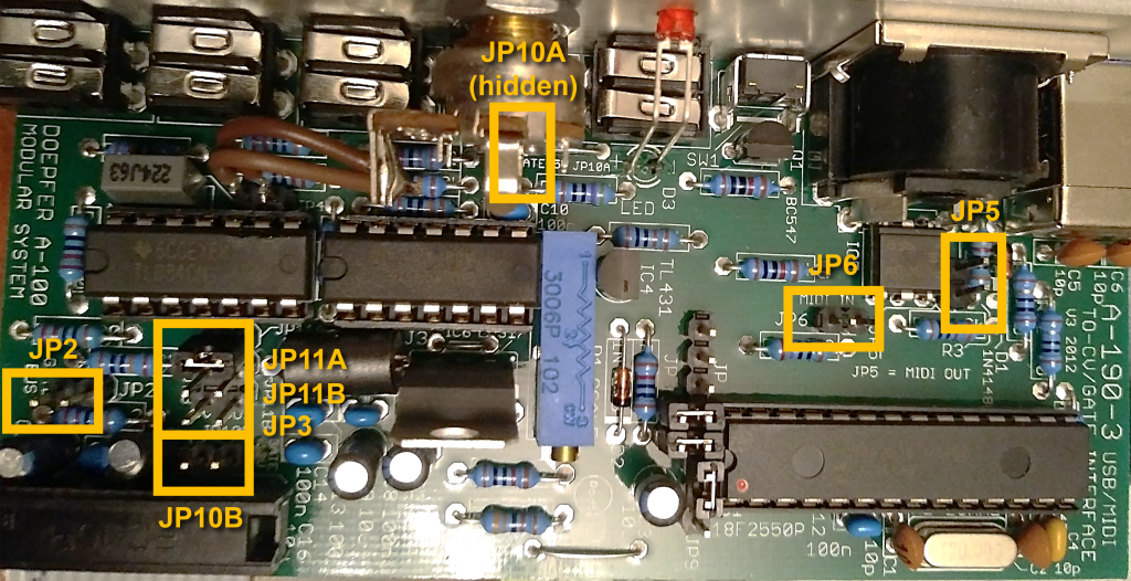
Configuration via the board
As usual with newer Doepfer modules, some options can be set via jumpers on the board. As with the predecessor A-190-2, the gate or CV note outputs can be output directly to the A-100 bus, so that adjacent built-in VCOs or ADSR generators can be addressed without cabling.
Make sure that the A-190-3 is the only module that “writes” to the bus, otherwise there will be a short circuit that can damage the modules.
Two other options were not yet available in the predecessor: The level of the gate voltage: 5 volts or 12 volts – and the range of the control voltage from the CV pitch output (MIDI pitch bend wheel): -2.5 volts … +2.5 volts or 0 volts … + 5 volts.
| Jumper: | Function: |
|---|---|
| JP2 | Jumper set: Connection of the Gate output to the A-100 bus. |
| JP3 | Jumper set: Connection of the CV Note output to the A-100 bus. |
| JP5 | MIDI connection (output) with another A-190-3 module. |
| JP6 | MIDI connection (input) with another A-190-3 module |
| JP10A JP10B | Setting of the gate output voltage. Jumper on JP10A: 5 volts (default), jumper on JP10B: 12 volts |
| JP11A JP11B | Voltage range for the CV Pitch output. Jumper on JP11A: -2.5 … +2.5 volts (default), jumper on JP11B: 0 … +5 volts. |
Technical specifications
| Width | 6 HP |
| Depth | 55 mm |
| Power requirements | 60 mA (+12V) / -10 mA (-12V) |