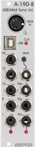
The A-190-8 is a midi interface specialized in converting midi clock signals into differently divided triggers for the A-100 system. In addition, the Midi start, continue and stop commands are converted into trigger or gate signals, so that analog sequencers in the modular system can be very easily synchronized with a DAW or a groove box.
The standard DIN socket or a USB input can be used as a MIDI input for the module. Other midi data such as notes etc. are not converted by this interface, so we are dealing here with an addition to one of the conventional midi interfaces and not with an alternative.
User interface
Inputs:
Outputs:
Controls:
Configuration via the board
The A-190-8 has a number of jumpers that can be used to further customize the module.
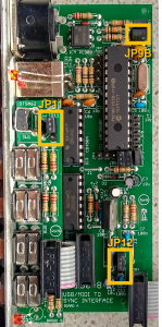
- JP9B: “Start” output signal as a trigger or as a gate. If the jumper is set (factory setting), a continuous gate signal is generated at the “Sta” output as soon as a midi start or midi continue command has been received. The gate signal only breaks off when a midi stop command has been received. If the jumper is removed, the “Sta” output only emits a short trigger signal when the module receives a start or continue command via Midi.
- JP11: External triggering of the “Wait” function by a gate signal or a simple short circuit. In the upper position of the jumper (factory setting), the “Wait” function is triggered by a gate or trigger signal (e.g. from an A-155 sequencer). If the jumper is in the lower position, the “Wait” function is triggered by a simple short circuit at the “Wait” socket, e.g. by a closing passive foot switch.
- JP12: Selection of the level of the output voltage (affects all outputs). In the upper position of the jumper (factory setting), +5 V are used at all outputs of the module (clock signals, reset, stop, start). This voltage is sufficient for controlling the Doepfer A-100 sequencer, envelopes, etc. Modules from other manufacturers sometimes require a higher voltage. In this case, the jumper should be placed in the lower position – then +12 V will be used for all outputs.
In order to use the A-190-8 interface to control DIN SYNC devices, a special cable is required that connects Start/Stop to the first pin of the DIN connector. The output of “Start” from the A-190-8 must be configured with JP9B set as the gate. The ground goes to the third pin and the undivided midi clock signal from the “96” output goes to the fifth pin.
Attention: Doepfer points out that when controlling DIN SYNC devices such as old Roland drum computers, like the TR808, via the A-190-8 interface, the voltage must only be +5 V (JP12 in the upper position) .
4/4 time!
The division of the midi clock is based on a 4/4 beat. This “fits” probably 99% of all “synthesizer music”, but requires some rethinking when using odd or slightly unusual time signatures like 3/4 time, 7/8 time, etc.
In any case, the output “96” outputs 24 triggers per quarter note, with a 3/4 time this is of course not 96 triggers per bar, but only 72 triggers. When controlling an A-155 sequencer, this will normally not be noticed at all, the notes generated by the A-155 naturally remain in sync with the DAW or a hardware sequencer or drum computer, which deliver the midi signal, even in 3/4 time. A quarter note is always a quarter note, so everything is fine here.
However, the “Wait” function, which also assumes a 4/4 beat, can be problematic: clock-synchronous stopping and restarting actually only works with a 4/4 beat exactly at the end or beginning of a beat. With other time signatures, the possible stop or start time of the analog sequencer shifts with each measure (in the case of a 3/4 time signature, e.g. a quarter note forward for each measure).
Thinking the other way around, you can of course use something like this for the creation and live processing of polyrhythmic structures. Of course, stopping and restarting the A-100 sequencer will always be in sync with a smooth quarter note, so that e.g. a combination of an 8/8 sequence in the A-155 with a 5/4 time signature in the DAW can deliver interesting results.
Alternatives
The very extensive options of the A-190-8 for various clock dividers and control triggers cannot be found in any other midi interface. The modules A-190-1 (discontinued model) and the successor A-190-4 have a simple clock and a reset output.
Technical specifications
| Width | 6 HP |
| Depth | 50 mm |
| Power requirements | 50 mA (+12V) / -0 mA (-12V) |