First of all: Wow, what a pompous name! “Quadrature Thru Zero VCO”! That sounds at least like Warp 11, quantum flux compensators and things like that, doesn’t it? The name is actually only topped by the A-110-6 “Trapezoid Thru Zero Quadrature VCO” – we’ll talk about that in a later blog post in this hyperspace continuum.
We know the word “Quadrature” from another module, the A-143-9 VC Quadrature LFO: Here, Doepfer offered an oscillator for the first time that generates a sine wave “quadratically”, i.e. with a phase shift of 90°. And so the A-110-4 also outputs a sine and a cosine (shifted by 90° against the sine). And “Thru Zero”? This simply means that the oscillator can be modulated down to true 0 Hz – here the oscillation simply remains at a constant voltage – and even lower to “negative frequencies”. The latter, however, are quite trivial again, they are simply inverted oscillations that increase in frequency again after crossing zero.
Why would you need something like this? The A-143-9 VC Quadrature LFO, for example, is often used for more complex modulations in which several modulation targets (e.g. VCAs or VCFs) are to be modulated differently but in constant mutual dependence. In principle, this can of course also be done with an A-110-4, but it can penetrate much further into the audio area. The A-143-9, on the other hand, is more of a “pimped” LFO. In addition, temperature compensation is built into the A-110-4, so the tuning is maintained even if the outside temperature fluctuates. FM with several oscillators is therefore closer – also interesting due to the modulation over the zero point.
User interface
Inputs:
System bus: As with the A-110-1 or A-111-1, the pitch of the A-110-4 can be controlled via a voltage applied to the system bus. The system bus can be addressed with an A-185-1 or A-185-2 or, if necessary, deactivated with a jumper on the circuit board.
As with all VCOs with CV control via the bus, you should deactivate this option if you are not using it: Otherwise, the open lines could work as “antennas” and pick up interference signals.
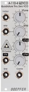
- 1 V/Oct: Exponential control voltage input. This input corresponds to the main control inputs of other VCOs and can be used with a CV keyboard or a sequencer, for example.
- XFM: This control input also works exponentially, but has an attenuator (“XFM” control) with which the control voltage applied here can be regulated, e.g. for a vibrato from the control voltage of an LFO.
- LFM: In contrast to the other two control inputs, the “LFM” input works linearly, so it is ideally suited for linear frequency modulation, e.g. with a second A-110-4.
Outputs:
- Sine: Audio output for the oscillator’s sine signal.
- Cosine: Audio output for the cosine signal (i.e. a 90° phase-shifted sine signal) of the oscillator.
Controls:
- XTune: This control is used to set the basic frequency of the oscillator. The control range is enormous, so fine tuning requires a little more sensitivity than, for example, with the A-111, which has two controls for coarse and fine tuning in addition to an octave selector switch.
- XFM: Attenuator for the exponential control voltage input “XFM”.
- LFrq: A linear controller for the frequency of the oscillator, which – in contrast to the “XTune” controller – can also go through the “zero point”: The frequency of the oscillator reaches 0 Hz around the middle of the control position and below that the frequency increases again, but with the inverted phase of the audio signal.
- LFM: Attenuator for the linear control voltage input “LFM”.
Pitch fluctuations from FM?
Linear frequency modulation can create very complex sounds that we have been familiar with since the Yamaha DX synthesizers of the 1980s. However, almost all FM synthesizers work with digital sound generation, analogue FM is considered to be a rather difficult art. Why?
One of the main problems are so-called DC offsets in the modulating VCOs: Many analog VCOs do not oscillate exactly around 0 volts, but show a slight offset that sometimes even varies depending on the frequency. This isn’t really a problem for an audio signal, we simply don’t hear any of these offset voltages. Quite different if you use something like this as a modulation signal: The slight additional DC voltage (and nothing else is such an offset) shifts the pitch of the modulated VCO a bit up or down. And if we increase the intensity of the modulation, then the fundamental frequency of the modulated VCO shifts even further. This is particularly noticeable when the modulation is dynamic, i.e. when in classic FM fashion we control the amount of modulation via a VCA with an envelope – the base pitch will then follow the envelope, an effect that we usually didn’t intend…
There are some reports online that our A-110-4 seems to be particularly sensitive to such DC offsets. What can we do? There are several solution approaches:
- Choosing a modulator (i.e. a VCO that modulates the A-110-4) that has the lowest possible DC offset. The only thing that helps here is trying…
- Insertion of a high-pass filter. An A-123 or an A-123-2 can mitigate the unwanted effect.
- Insertion of a capacitor: This is a solution for soldering friends, but it also has its limits with dynamic modulation – a DC offset that is modulated via VCA and envelope is no longer a real DC voltage that a capacitor could eliminate.
- Compensation of the DC offset with an added DC voltage – here too we fail with dynamic modulation.
- We accept the problem as it is and use the A-110-4 with dynamic FM more for effect sounds, percussive sounds and other things that don’t have to follow an exact pitch.
At the end of the day, these are all compromises. For dynamic FM to be played tonally, the A-110-6 – albeit more expensive – is the much better choice.
Frequency shifter
A Doepfer module that is unfortunately no longer in production is the A-126 VC Frequency Shifter: a complex device with which the partials of a waveform can be shifted up and/or down by a certain amount. Since this shift changes all partials by the same frequency, the original harmonic structure is lost and bell-like sounds are produced, as are known from ring modulators.
In fact, a frequency shifter can be simulated using a quadrature oscillator and two ring modulators (e.g. from an A-114 Dual Ring Modulator or – more finely adjustable – from an A-133 or A-133-2 Dual VC Polarizer). The sine and cosine oscillations from the A-110-4 serve as one of the input signals for the A-114 and as a modulation signal for the A-133. The audio signal to be modulated is then routed to the two free inputs of the A-114 or A-133 (divided by multiples).
The typical frequency shifter signals are a “shifted up” and a “shifted down” signal, which we get from a simple 1:1 mix (up) of the two ring-modulated signals, and from a mixture of an original signal with an inverted signal. Our replica requires a little more space than the original, but comes with “bread-and-butter” modules (A-114, A-175 Our replica requires a little more space than the original, but comes with “bread-and-butter” modules (etc.) throughout, which should also be present in smaller modular systems. Unlike the original A-126, which only had a very simple quadrature oscillator “on board”, with the A-110-4 we can also use extremely low modulation frequencies and create fascinating beats that are not easily possible with the original.
The new A-126-2 Frequency Shifter offers (among many other improvements) inputs for an external quadrature VCO/LFO with its sine/cosine signals.
FM – frequency modulation
“FM” is usually understood to mean a frequency modulation of oscillators (in contrast to a “filter FM”, for example), which works with modulation frequencies in the audio range. The principle is known from Yamaha’s digital FM synthesizers, although technically this FM is more of a phase modulation.
FM sounds can already be created with another VCO (e.g. an A-110-1) as a modulator, which sound very unusual due to the “Thru Zero” feature and the resulting ongoing phase reversal (in the audio range!). Incidentally, you should also use waveforms other than just sine waves as the modulator waveform. Pulse waves in particular lead to very attractive results.
The core of the matter
The A-110-4 is one of the few oscillators (besides the A-143-9) that has a real sine wave core. This means that the sine wave here is not made up of another waveform (usually a triangle as with the A-111-1, A-111-2 and A-111-3 or a sawtooth as with the A-110-1 and A-110-2), but is basically already generated as a sine. Accordingly, the sine of the A-110-4 – VCOs is very clean and without “corners and edges” that may produce additional overtones as a side effect – which are unwanted with the sine.
Temperature compensation
The A-110-4 features a small temperature compensation circuit that keeps it in tune regardless of changes in outside temperature.
Special edition
The A-110-4 is also available in a special edition with a blue front panel and white rotary controls.
Sound examples
-
A-110-4, A-110-6, A-133-2 / Modulation in the polarizer
In this sound example, the two 90 degree phase-shifted sawtooth outputs of the A-110-6 are modulated in an A-133-2 VC polarizer by the sine and cosine outputs of an A-110-4. In principle, this is an amplitude modulation that changes phase when the control voltage is negative (ring modulator principle). We hear the two outputs of the polarizer distributed to the stereo channels. The tuning of the two VCOs is controlled by hand.
A-110-6 in the VC polarizer, modulated by an A-110-4. -
A-110-4, A-110-6, A-172 / Phase shifted in the Max/Min Selector
In this example we use an A-110-6 and an A-110-4 with their sine outputs each phase-shifted by 90 degrees. The aim is the four input signals of an A-172 Max/Min Selector. The two outputs for Max and Min are distributed over the two stereo channels. My two A-110-4s are from an earlier series with a significantly lower output level than the A-110-6, which leads to interesting side effects here. The tuning of the two VCOs is again controlled by hand.
A-110-6 in the Max/Min, together with an A-110-4. -
A-110-4, A-133-2 / Double ring modulation
An A-110-4 modulates the two “CV” inputs of an A-133-2 Dual VC Polarizer with its sine and cosine outputs. The second input signal – into both “In” inputs of the A-133-2 is a constant frequency “TRASIN” waveform from an A-110-6.
With an A-138m Matrix Mixer, the two “Out” outputs of the A-133-2 are mixed 1:1 for the left audio channel, for the right audio channel a mixture of the normal “Out” output of the first sub-module in the A-133-2 and the inverted “Out” output of the second sub-module.
The frequency of the (ring) modulating A-110-4 is now manually increased from almost 0 Hertz to audio frequencies and back again. From about 0:25 the frequencies of the left and right channel drift apart audibly – the right channel gets deeper, the left one gets higher. This is an effect that is also known from much more complex frequency shifters.
Ring modulation.
Technical specifications
| Width | 8 HP |
| Depth | 60 mm |
| Power requirements | 90 mA (+12V) / -30 mA (-12V) |