The A-160-2 actually does exactly what I always wanted from a clock divider. It splits an incoming clock signal in a “musical” way. What does that mean? A simple clock divider like the old A-160-1 counts the input triggers, so to speak, and always divides them into two equal halves, depending on the division factor. For example, when dividing by 4, the clock divider will split four input triggers in half, i.e. it will output its own trigger from the third to the fourth input trigger (or until the end of its zero level). That’s exactly a quarter. At 1/8, the output trigger is activated by the fifth through eighth input triggers. And also this one (long) output trigger is exactly one eighth.
That’s mathematically correct, but most of the music we make ticks differently. When the input triggers correspond to quarter notes, we usually want the trigger divided by 4 to correspond to whole notes. There would then be a trigger on the first, fifth, ninth and thirteenth input trigger. And that’s exactly what the A-160-2 Clock/Trigger Divider does.
User interface
Inputs:
Outputs:
Controls:
How does the module divide?
Unlike the A-160-1, the A-160-2 generates its first output trigger on the first input trigger. This is closer to us musically because it generates the derived trigger “on the 1” and not later.
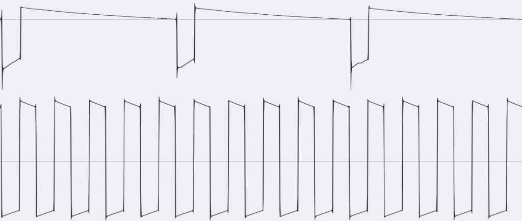
Let’s take a look at this in the “GATE” mode of the A-160-2 in the oscilloscope:
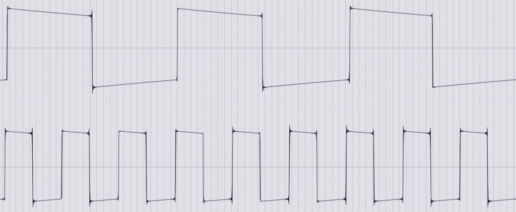
Like conventional clock dividers, the “GATE” mode always divides the input signals into two equal halves for its on and off signal. There is also a second mode “TRIG”, which takes the length of the input signal into the output signal:
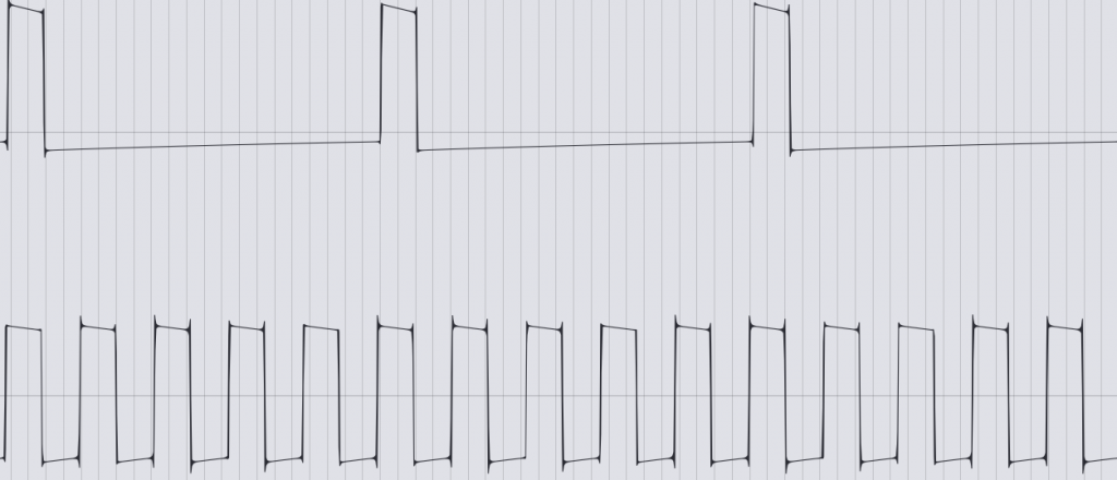
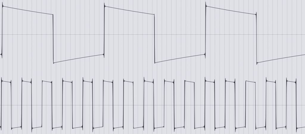
The custom mode “Cst” is not officially implemented yet, with my A-160-2 modules it outputs an inverted version of the “TRIG” mode, i.e. a short trigger signal at the corresponding “zero” phases of the input trigger.
Various division series
The usual frequency or clock dividers simply halve. This is an octave below for audio signals and half the speed for clock signals. You can repeat this multiple times and get more sub-octaves or 1/4 or 1/8, 1/16 etc. of the clock speed. The A-160-1 also works with the already known “oddities” in the output of the divided clock signals.
The A-160-2 also offers this – as one of 3 options. In the upper switch position for the division rows, it generates the divisions 1/2, 1/4, 1/8, 1/16, 1/32, 1/64 and 1/128 at the output sockets.
But the module can of course do more.
In the middle switch position, prime numbers are output as dividers: 1/2 (of course, they’re always there), 1/3 (the input clock is summarized as a triplet), 1/5, 1/7, 1/11, 1/13 and 1/17. Prime numbers as dividers lead to a maximum “drifting apart” of the rhythmic structure. For example, until an input clock divided by 11 and an input clock divided by 13 meet again at the same time, 11 x 13, i.e. 141 input clock signals, pass. This is ideal for polyrhythmic structures.
In the lower switch position, dividers are created that are increased by one: 1/2 (clear), 1/3, 1/4, 1/5, 1/6, 1/7 and 1/8. Here, most divisors meet more often than was the case with the prime numbers. So we’re on a little more familiar ground, but you can still build rhythmically interesting structures with it.
Configuration via the board
As usual with the newer Doepfer modules, the A-160-2 can also be configured in detail using jumpers on the circuit board.
Note: The two jumpers on the far left are currently not used, the two jumpers on the far right must always remain unused (without jumpers attached).
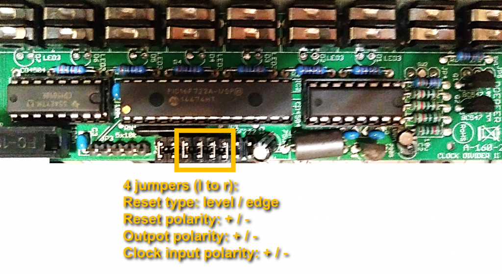
The usable jumpers from left to right:
- Reset type: If the jumper is set, a reset is carried out after a certain voltage has been exceeded or fallen below. With a triangle or sine as the reset signal, the reset is slightly delayed. Without a jumper, an attempt is made to detect a rising edge (or falling edge in the case of negative polarity of the reset signal) and to use it as a trigger.
- Reset polarity: If the jumper is set, the reset occurs when a voltage is exceeded or the input signal rises (depending on the reset type). Without jumper: when the voltage falls below a certain level or the input signal falls.
- Output polarity: If the jumper is set, the divided clock signals are output as “normal”, positive triggers. Without jumpers, the output triggers are inverted (i.e. a trigger is output where there would normally be a “pause”).
- Clock input polarity: If the jumper is set, the module reacts to “normal”, positive clock signals. Without a jumper, the clock signal is inverted, i.e. the “pauses” between the clock signals are used as triggers.
In the factory state, all 4 jumpers are set, the alternative configurations in this case are more for “exotic” possible uses of the module.
Sound examples: Rhythmic structures
For the sound examples, an input trigger is obtained from an A-155 sequencer (which, apart from the trigger signals, contributes nothing else). Several outputs of the A-160-2 trigger the decay envelopes of an A-142-4 Quad Decay, which in turn control four amplifiers in two A-132-3 VCAs. Sound material for the VCAs: Digital and analogue noise generators, an A-105 filter as a “bass drum”, some post-processing with filters and a BBD.
The first example uses the “normal” division in quadratic steps, as known from the A-160-1.
In the next example we use the division by consecutive numbers. The result is already a bit more complex.
Finally, we use division by prime numbers. Very complex rhythms are created here, which take a comparatively long time until something is repeated.
Technical specifications
| Width | 4 HP |
| Depth | 35 mm |
| Power requirements | 50 mA (+12V) / -0 mA (-12V) |