
The A-106-1 Xtreme Filter is a real fun box! The technical design is inspired by the filters of the Korg MS-20, but goes very far beyond them: Very differentiated controllable clipping (distortion) of the filter resonance, separate inputs for low-pass and high-pass mode (comparable to the A-101-1 Vactrol filter), as well as a separable feedback path (similar to the A-108 48dB filter).
In terms of sound, the module is quite special, the resonance distorts heavily, the filters (a 12 dB low-pass and a 6 dB high-pass) do not close completely and otherwise do not necessarily do what one would expect from a “well built” filter. But nobody wants that with a filter that is based on the MS-20.
User interface
Inputs:
- CV1: Control voltage input for the cutoff-frequency (without attenuator).
- CV2: Control voltage input for the cutoff-frequency (with a simple attenuator).
- CV3: Control voltage input for the cutoff-frequency (with bipolar attenuator).
- LP In: Audio input for the module’s lowpass filter.
- HP In: Audio input for the highpass filter of the module, designed as a switching socket: If there is no plug (from a sound source or a dummy plug without any further connection), the signal from the lowpass filter is passed on to the highpass filter.
- Res. Insert In: Audio input into the filter’s feedback path, which is used to generate the filter resonance through selective feedback.
Outputs:
- Res. Insert Out: Audio output for the filter feedback loop. Additional sound processing modules can be connected between the output and input of the feedback loop.
- Out: Audio output for the filtered signal.
Controls:
- Frequ.: Controller for the cutoff-frequency (applies equally to the lowpass and highpass filters).
- CV2: Attenuator for the control voltage for the cutoff-frequency from “CV2”.
- CV3: Attenuator for the control voltage for the cutoff-frequency from “CV3”. The controller works bipolar, i.e. the input signal is inverted at controller positions to the left of “12 o’clock”.
- LP Lev: Attenuator for the audio signal at the “LP In” input.
- HP Lev: Attenuator for the audio signal at the “HP In” input, or for the “LP In” input if the switching socket is not assigned. The controller works bipolar, to the left of “12 o’clock” the input signal is inverted.
- CL+: Controller for the clipping (distortion) of the input signal – here for the positive part of the waveform. The clipping is extremely soft and harmonious (no “hard clipping”). At controller position “0” maximum clipping takes place.
- CL-: Controller for the clipping of the input signal – here for the negative part of the waveform.
- Res.: Controller for the resonance of the filter. If the “Res. Insert” sockets are used for an external feedback loop, the input is controlled here (lower socket).
Possible uses
The filter is certainly not a “bread and butter” filter for standard sounds. But when you want it to sound a bit wacky or trashy, the Xtreme Filter shines.
Separate inputs for LP and HP
Like the A-101-1 Vactrol Multitype Filter, our A-106-1 has separate inputs for lowpass and highpass filtering. The HP input is normalized to the LP input via a switching socket. As with the A-101-1, this can be used to simultaneously use a higher transposed VCO for the LP input and a lower transposed VCO for the HP input. Two octaves apart is a very useful starting point for then driving through a very wide sound spectrum with a far-reaching filter sweep.
Common cutoff-frequency for LP and HP
The high-pass and low-pass modes are not two separate filters, but share both the cutoff frequency and the resonance. Nevertheless, the combination in particular allows for interesting sounds, e.g. the bipolar “HP Lev.” control can be used to manually crossfade between the notch and bandpass filters. But you shouldn’t expect “conventional” notch or band passes, the permeability / crosstalk between HP and LP is high. If this crossfade is not to be manual but voltage-controlled, a VC polarizer (A-133) is connected in front of one of the two inputs and both input attenuators are set to approximately equal positive values:

Clipping
The clipping of the input signal can be controlled separately for the upper and lower part of the waveform (each in a counter-clockwise direction). Clipping is usually understood to mean relatively hard cutting/smoothing of the waveforms on the positive (Cl+) or negative (Cl-) part of the waveform. With extreme settings, almost every input signal approaches a square wave.
Our A-106-1 doesn’t work quite as hard, the clipped waveforms are rounded off quite noticeably. The result is not “sawing” like a very hard clipping, but rather soft and harmonious.
This can be used to generate asymmetrical waveforms such as with the A-116. Unfortunately, the two clipping controls are designed in a somewhat counter-intuitive manner: maximum clipping occurs at control position “0”, and no clipping at all at “10”.
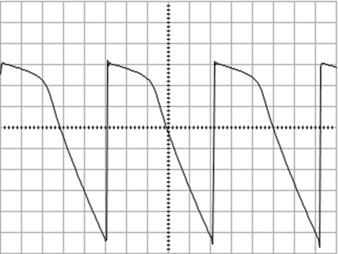
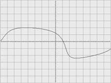
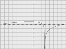
Self-Oscillation and Clipping
Filters normally produce comparatively pure sine waves during self-oscillation. Normally. Our A-106-1 also goes its own way here.
The following oscilloscope images show the waveforms that occur when the filter self-oscillates with different settings of the two clipping controls:


Open Resonance Path

A special feature (similar to the A-108) is the open resonance path: Here, a voltage-controlled resonance can be implemented via a VCA or simply loop in another module.
MS-20 Reloaded?

The filter section of the MS-20 can be recreated with two A-106-1 modules – the result will of course sound a little different than the original (which, by the way, was manufactured with two quite differently built and sounding filter sections during its production time).
Of course, this does not mean that you have an MS-20, the oscillators were quite special, one of the envelopes had a delay, the LFO had a variable waveform that could be changed between ascending sawtooth, triangle, descending sawtooth and any intermediate stages, etc.
Basically, if you want a “really real” MS-20, you should get an MS-20 (or an inexpensive replica). If you want the tonal characteristics of the MS-20 (and much more) in a modular system, the A-106-6 is the perfect choice.
Sound examples
-
A-106-1 / Oscillators divided between both inputs
Two A-110-1 VCOs are transposed to an interval of 2 octaves and controlled together by an A-155 sequencer. The sawtooth from the lower-tuned VCO is sent to the high-pass input, the sawtooth from the higher-tuned VCO to the low-pass input of the A-106-1 (level approx. 5 in each case). CL+ is set to 10, CL- to 0. The filter’s output signal is amplified (exponentially) via an A-132-3 VCA. The VCA is modulated by an A-140 ADSR, which is triggered by the sequencer.
The cutoff-frequency of the A-106-1 is modulated by the triangle signal from a slow A-143-3. You can hear – with a lot of crosstalk between the filters – how the lower and the higher tuned VCO slowly alternately dominate the sound. The resonance of the filter is initially 0 and is adjusted to the maximum in the course of the sound example.
Two VCOs separately in the two inputs of the filter. -
A-106-1 / Input signal via polarizer
A single A-110-1 VCO provides the basic material for the sound. The sawtooth output is split: one part goes directly into the lowpass input of the A-106-1 filter, the other part is sent through an A-133 VC polarizer before going into the filter’s highpass input. The polarizer is modulated by a slow triangle signal from an A-143-4 LFO. The levels of both inputs in the filter are set to 5.
The VCO is controlled by an A-155 sequencer, which also triggers an A-140 ADSR. The ADSR simultaneously modulates an A-132-3 VCA (exponentially) for the filter’s output signal and the filter’s cutoff frequency. Both clipping controls in the filter are set to 10.
During the sound example, the resonance is slowly regulated from 0 to maximum. Due to the modulated polarization of the second (identical) input signal, you can hear a slow fade between lowpass (HP input signal at 0), bandpass (HP input signal positive) and notch (HP input signal inverted). Admittedly, with the A-106-1 these differences are rather subtle due to the crosstalk between the filters and the always “contributing” distortions.
Split input signal with modulated polarizer. -
A-106-1 / BBD in the feedback loop
Three A-110-1 VCOs serve as raw material, two sawtooth waves are slightly detuned, one octave below is a sine wave. The mix (using an A-138b) goes into the LP input of the A-106-1, the HP input is muted with a dummy plug.
The VCOs are controlled by an A-155 sequencer with an A-160-5 ratcheting controller providing the trigger signals for an A-140 ADSR. The ADSR modulates an A-132-3 VCA (exponentially) after the filter, as well as the cutoff-frequency of the filter. Additionally, the filter is controlled by the pitch control voltage from the sequencer (attenuated).
An A-188-1X BBD with 128 stages is looped into the filter’s feedback path. The BBD is modulated by a slow triangle wave from an A-143-4 LFO.
During the sound example, I start with no feedback in the filter and slowly increase it to the maximum manually. After that I also increase the BBD internal feedback loop from 0 to the maximum. The cutoff frequency of the filter is then manually increased, the BBD feedback is turned back to 0 and then the filter feedback is also reduced to 0 again. At the end, the filter modulation by the ADSR generator is reduced to 0.
Some reverb and delay from the DAW.
A BBD in the feedback loop. -
A-106-1 / Single and double use
Two A-106-1 are used in this sound example. We start again with 3 A-110-1 VCOs, all using the sawtooth outputs, one VCO transposed 1 octave down. The mix of the 3 VCOs goes into the first A-106-1 (in high-pass mode) and then into the second A-106-1 (in low-pass mode). Pitches of the VCOs and triggers for the ADSRs are controlled by an A-155 sequencer. Different clipping levels of the filters are controlled manually.
During the first 2 minutes only a single A-106-1 is in use, after that we switch to 2 filters – first highpass, then lowpass:
Two A-106-1.
Technical specifications
| Width | 14 HP |
| Depth | 40 mm |
| Power requirements | 30 mA (+12V) / -20 mA (-12V) |