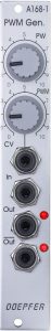
The A-168-1 is a small auxiliary module that generates a square or pulse oscillation that can be modulated in width for LFOs or VCOs without a square/pulse. This is an interesting feature for LFOs in particular, since almost all LFOs can generate a fixed, symmetrical square wave (at least the A-146 is capable of manually adjustable pulse widths), but none allows pulse width modulation.
Things are a little more relaxed with the VCOs: Except for the two “Thru Zero” VCOs A-110-4 and A-110-6, all Doepfer VCOs are capable of variable pulse widths and their modulation via control voltages.
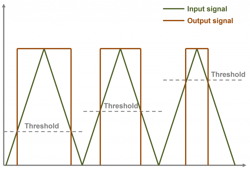
Internally, a comparator circuit works as in the A-167, which generates a gate signal when a voltage is exceeded and terminates it again when the voltage falls below this gate. The variable pulse width results from different threshold values at which the gate is triggered. This also makes it clear that for a variable pulse width, at least one flat rising or falling edge is required for the input signal (triangle, sine, sawtooth, ADSR envelopes, etc.) – with a rectangle as the input signal, only this rectangle can be generated again (which would make little sense).
User interface
Inputs:
Outputs:
The outputs for normal and inverted signal are reversed.
Controls:
How about the rectangles?
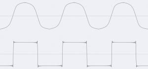
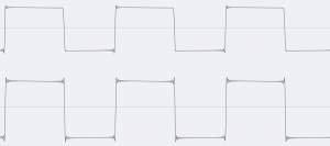
For example, if you use an A-110-1 as the input signal, then you can look at the square waves derived from different input signals very nicely on the oscilloscope (or in the enlarged view of the DAW recording). Above is the input signal and below is the output signal from the “inverted” output (which is in phase, however, the inverted signal is present at the “standard” output):
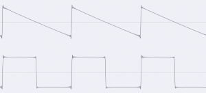
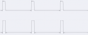
The “PW” controller is always in the middle, with sine, triangle and sawtooth you can use it to set the pulse width of the output signal. If a square-wave or pulse signal is used as the input signal, this of course no longer works due to the principle involved. Whatever threshold is used, it will be immediately exceeded on the rising edge of the incoming rectangle and immediately undershot on the falling edge. Correspondingly, a pulse oscillation as an input signal also generates a pulse oscillation as an output signal (of course with the same width).
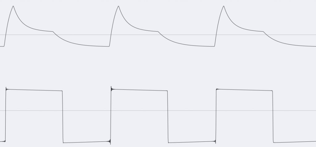
Sound example: Envelope as input signal and PWM
An A-140 ADSR envelope is triggered by a fast A-143-3 LFO so that it outputs an audio signal itself. Due to the purely positive voltage of the envelope, the “PW” controller must be set comparatively far to the left. A modulation of the pulse width (through a slow A-110-6 – sine wave) is also only possible in a narrow control range, then the internal threshold value obviously falls below 0V and the signal breaks off. We hear the constant ADSR signal on the left and the output of the A-168-1 on the right:
“Poor Man’s” A-167?
The A-167 was a reasonably complex but also very flexible tool that is unfortunately no longer manufactured. Like the A-168-1, it basically consists of a comparator, but is equipped with additional functions that are far more comprehensive (two adjustable inputs plus internal positive or negative offset voltage, hysteresis function for different switch-on and switch-off voltages, etc.)
In order to replicate the A-167, the A-168-1 would have to be supplemented with at least an A-183-2 offset polarizer, perhaps also an A-138c polarizing mixer and an A-183-3 amplifier.
Things get a little trickier with the A-167‘s “Gap” control. It simultaneously shifts the threshold up at the start of the generated gate signal and down at its end. Here you could experiment with a slew limiter like the A-170, which “smoothes” the input oscillation accordingly.
Configuration via the board
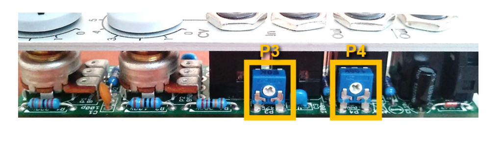
This time we don’t find any jumpers for optional functions on the small circuit board, but rather two trimming potentiometers for adapting to different input modules. You can see that the concept is not so much a comparator that can be used in general, but – nomen est omen – a PWM generator that is relatively firmly assigned to a specific VCO or LFO.
- P4: The offset voltage at the center stop of the “PW” controller is set here. The factory setting should be fine for VCO signals, but you have to adjust this when using an ADSR generator (which only supplies positive voltages). If you don’t want that, you can also switch an A-183-2 between the input signal and the PWM generator.
- P3: The amplification of the control voltage is set here. In the case of very weak input signals, real amplification may have to take place here. If you don’t want to work with the trim pot, you can alternatively use an A-183-3 between the modulation source and the PWM generator.
Technical specifications
| Width | 4 HP |
| Depth | 20 mm |
| Power requirements | 20 mA (+12V) / -20 mA (-12V) |