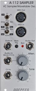
The A-112 is a small digital module that can record, store and play back transposed audio material – a sampler in small format. In addition, the module can also be used for simple wavetable synthesis and as an effects device.
The module has two small memory banks (each 64 kbytes in size) to store audio material and play it back in different ways. One of the two memories can also be used for digital effects (pitch shifting, delay and reverse delay). Due to the low resolution of 8 bits, all of this has a clear retro charm, since the conversion (analog / digital and back again) already changes the audio material in the sound. So the A-112 is definitely not a “high-end” sampler – computers are much better suited for that.
A disadvantage of the module is its “somewhat” cryptic user interface: Switches and some input sockets are assigned multiple times and with very different functions, so you will have to estimate a certain amount of familiarization time.
By the way, I think my original description in the book is pretty mediocre, so this post has been largely rewritten.
User interface
Due to the multiple assignment of switches and sockets, the module takes some getting used to when operating. No display or even an opulent DAW interface helps, some changes between different operating modes do not work without intermediate steps that you just have to remember. You should therefore reckon with a little more training time than for other modules.
Inputs:
- Gate In: Input for a gate signal to play back the recorded audio material.
- Audio In / Wave-CV In: This input is used differently depending on the operating mode – as an audio input when recording audio material into the memory of the A-112 or as a control voltage input for sweeping through the waveforms in wavetable mode.
- CV In for controlling the pitch of the oscillator in “normal” sampler mode.
- MIDI In: Midi input for transferring sample dumps, e.g. from a computer to the memory of the A-112.
Outputs:
- MIDI Out: A MIDI sample dump of the recorded audio material can be output here.
- Audio Out: Audio output of the module.
Controls:
- Eff / S1 / S2 switch for using the A-112 as an effects device (Eff) or with one of the two memory banks S1 and S2 as a sampler or as a wavetable oscillator that can move through audio material using a control voltage.
- Dmp / Play / Rec (Pit / Del / Rev) switch for the sampler functions Sample Dump, Playback and Recording, as well as (when the switch above is in the appropriate position) for the Pitch Shifter, Delay and Reverse Delay effects. Then the position of the switch underneath is also relevant.
- Switch Loop / Norm / Wav (Len / Norm / Frz) for further options / operating modes, especially in effect mode (e.g. for a freeze effect).
- Man. Trig. Button for triggering the sampled audio material (in sampler mode).
- The Atten. controller is an attenuator for the audio input.
- Tune controller: setting the tuning (pitch) of the sampler.
What can the module do?
The A-112 can work as a classic-style sampler, can run through its internal memories in the sense of a flexible wavetable oscillator and also process audio material in real time with digital delay effects, freezing and pitch shifting. And all of this based on a technical platform from 1998, including voltage control in the modular system.
The A-112 as a sampler or wavetable oscillator
For these operating modes, the two memory banks S1 and S2 are used alternatively to store audio material and output it again in different ways.
Preparation for use: recording
To record an audio signal for the sampler or wavetable oscillator, the following steps are required:
- Use the top switch to select one of the two memory banks S1 or S2 to be recorded into.
- Select “Rec” with the middle switch.
- Select “Norm” with the bottom switch. (We’ll talk about other recording methods later.)
- Set the desired sampling frequency using the “Tune” control. The higher the frequency, the more realistic but also shorter the recording. The range is from 2 kHz to 79.4 kHz.
- The audio signal must be present at the “Audio In / Wave-CV In” input.
- As long as there is no gate signal at “Gate In”, we have a preview signal at the output. In case of clipping, the “Run” LED flashes briefly.
- Start recording via a gate signal at the “Gate In” input or by pressing (and holding down!) the “Man. Trig” button. The audio material is recorded until either the memory is full or the gate signal is interrupted. If the gate signal is active, it is no longer possible to change the sampling frequency during recording.
Each of the two memory banks S1 and S2 has 64 kbytes of storage space, each with 256 “pages” of 256 bytes each, which can be addressed individually as “waves” in wavetable mode. This means that around 2 seconds of audio material can be recorded per memory bank at a sampling frequency of 32 kHz.
Other types of recording
If the bottom switch is not set to “Norm”, there are other recording options:
- “Loop”: The recording is not automatically aborted when the memory is full, but starts again at the beginning and overwrites memory areas that have already been recorded. The recording only ends when the gate signal stops.
- “Wav”: Only a 256-byte “wave” is recorded here. As with the other two types of recording, the sampling frequency is determined via the “Tune” control or the control voltage at “CV In”, as long as there is no gate signal. However, as soon as we have an active gate signal, “Tune” or “CV In” determine the number of the page in which the wave is recorded. This memory position is then continuously overwritten with the audio material until the gate signal is interrupted or another memory position is selected via “Tune” or “CV In”. This allows a complex (albeit difficult to predict) wavetable to be generated in memory from a longer audio signal and a control voltage, e.g. from an ADSR generator, an S&H, etc. A conventional recording in “norm” mode, which is then played back in wavetable mode using a control voltage, is certainly easier.
Playing samples / wavetables
The audio material recorded in this way can now be played back either as a one-off run through the entire memory (One Shot), in a continuous loop of the entire memory (Loop) or selectively. With selective playback, individual “waves” from the memory are played back in an endless loop. It is possible to set the memory address of the wave to be played back dynamically (wavetable oscillator), you can “drive” forwards and backwards through the audio material or “stop” at a single recorded waveform. This then corresponds to one of the “pages” mentioned above, each with a size of 256 bytes.
- The top switch remains on the previously set memory S1 or S2.
- Change the middle switch from “Rec” to “Play”.
- Set the type of playback with the lower switch:
- “Norm” for one-time playback of the memory contents,
- “Loop” for playback of the memory content in an endless loop,
- “Wave” for selective playback of individual waves or dynamic scrolling through the memory via a control voltage.
- Play: With a gate signal at the “Gate In” input or by pressing the “Man. Trig.” playback starts:
- With “Norm” the entire sample memory is played back to the end once, even if the gate signal is interrupted during playback. A new gate signal starts the playback process again from the beginning.
- With “Loop” the sample memory is played back in an “endless loop”, i.e. at the end of the playback we start again at the beginning. As soon as the gate signal breaks off, however, playback does not end! Instead, from then on, the sample memory is played back in an endless loop from the beginning to the last point reached. A new gate signal extends the playback loop again until the next gate signal is interrupted. Playback in “Loop” mode is only ended when a short trigger signal of max. 100 ms is applied. Complicated? Yes…
- With “Wave” the A-112 works as a wavetable oscillator. The selected wave (i.e. a 256 byte memory area) is played repeatedly until the gate signal is interrupted. Other pages can be selected via a control voltage at the “Audio In / Wave-CV In” input and thus the entire sample memory can be run through dynamically forwards or backwards or the playback can remain at a single wave.
- With all three types of playback, the sampling frequency and thus the pitch and at the same time the speed of playback can be controlled with a control voltage via “CV In” like with an analog VCO. In addition, the pitch (and speed / sampling frequency) can be influenced manually using the “Tune” control
Saving and loading sample contents
The recorded audio data of both memories S1 and S2 are retained even when the A-100 system is switched off. Sometimes that’s not enough, of course, and you want to work with a kind of “sample library” and reuse recorded sounds later. A simple midi sample dump function is implemented for this purpose.
- The memory S1 or S2, which is to be stored externally or loaded from an external source, is selected via the top switch.
- The middle switch is set to “Dmp” for the sample dump function.
- The bottom switch determines whether the entire memory S1 or S2 is transmitted (position “Norm“) or just a single wave with 256 bytes (position “Wav“). For individual waves, the “Tune” control (or a control voltage at “CV In”) determines which memory page is to be sent or loaded. A sample dump in the “Loop” mode of the lowest switch is not implemented, that would make no sense either.
- Transfer data from the A-112:
- A gate signal at the “Gate In” input or pressing “Man. Trig.” sends a sample dump to the “MIDI Out” output.
- Alternatively, a sample dump request (e.g. from a DAW) can be received via “MIDI In”, which triggers the sample dump at “MIDI Out”.
- Load external data into the A-112:
- With the switch positions described above, the A-112 is ready to receive a sample dump via “MIDI In”.
Unfortunately, the free downloadable sample dump program for the A-112, which also allows the conversion of Wav files, is now clearly outdated, it only works under DOS (or to a limited extent under Windows 95). Otherwise, Midi sample dumps are also possible with the program MIDI-OX (www.midiox.com) or with most DAWs.
MIDI dump request for the contents of memory S1 or S2:
F0
00 20 20
7F
00 or 01
F7
Start of sysex message
Doepfer Sysex ID
Recall memory of the A-112
00 = memory S1, 01 for S2
End of sysex message
MIDI dump request for individual waves:
F0
00 20 20
7D
[Bit 7-1 der Page] [Bit 0 der Page]
F7
Start of sysex message
Doepfer Sysex ID
A-112 Wave Recall
hexadecimal page number from 1-256 in 8 bits
End of sysex message
The A-112 as an effects device
The A-112 sampler / wavetable oscillator can also be used as an effects device. But you have to be aware that the 8-bit converter of the digital module also has its own “Lo-Fi” sound characteristics. The module offers pitch shifting, delay (with a maximum delay time of 2 seconds) and reverse delay. In addition, the output of one of the three effects can be “frozen” with Freeze.
Caution: When used as an effects device, the contents of memory S2 are overwritten.
Lo-Fi effects!
The A-112 can easily be used as a lo-fi effects processor: set the top switch to the “Eff.” The middle switch is used to select the type of effect: pitch shift (switch position “Pit”), delay (switch position “Del”) or reverse delay (switch position “Rev”). The bottom switch can be used to choose between normal (switch position “Norm”) and “Freeze” mode (switch position “Frz”).
Preparation for use as an effects device
Before using the effects, you must set the size of the memory to be used (the memory “S2” will be overwritten):
- Switch 1 to “Eff”.
- Switch 2 to one of the three effect types as required.
- Switch 3 to “Len”.
- Now set the desired memory size with the “Tune” control. A large memory area allows longer delay times.
This selection is activated by applying a gate signal to the gate input (or manually triggering the “Trig” button). The effects remain active for the duration of the gate signal, after which they are deactivated again.
Freeze mode:
For Delay, Reverse Delay and Pitch Shift there is also a “Freeze” mode that freezes the currently processed signal. However, to switch over, the “Norm” operating mode must first be aborted:
- Top switch from “Eff” to “S1” or “S2”, or
- lowest switch to “Len”.
After that, the lowest switch can be set to “Freeze”.
A change back from “Freeze” mode to normal mode must be done in the same way.
The sampling frequency (and thus the delay time for a given memory size) is controlled with the “Tune” control. The freeze effect for delay, reverse delay or pitch shift is only started with an active gate signal (“Gate In” or “Man. Trig.”).
Pitch Shifter:
Here, too, the “Tune” control is used to set a sampling frequency with which the previously specified memory is read out. However, the audio signals are still written to the memory with a fixed sampling frequency, so that this controller plays back the audio fragments that have just been saved too quickly or too slowly. The size of the previously specified memory determines the “granularity” of the effect. Here, too, the effect is activated by a gate signal (“Gate In” or “Man. Trig.”).
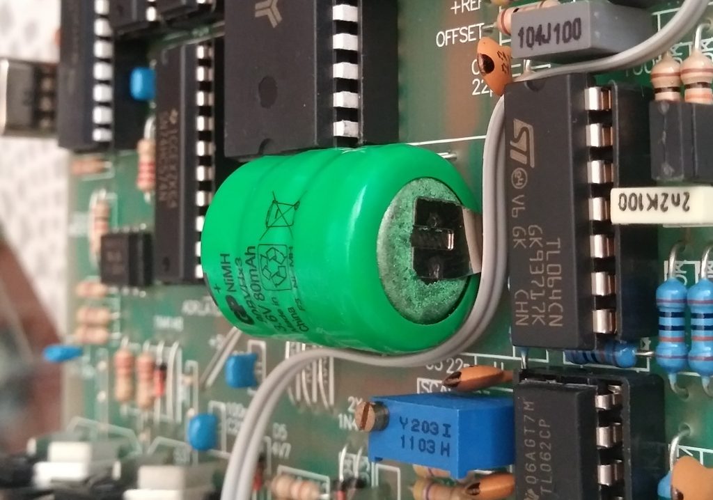
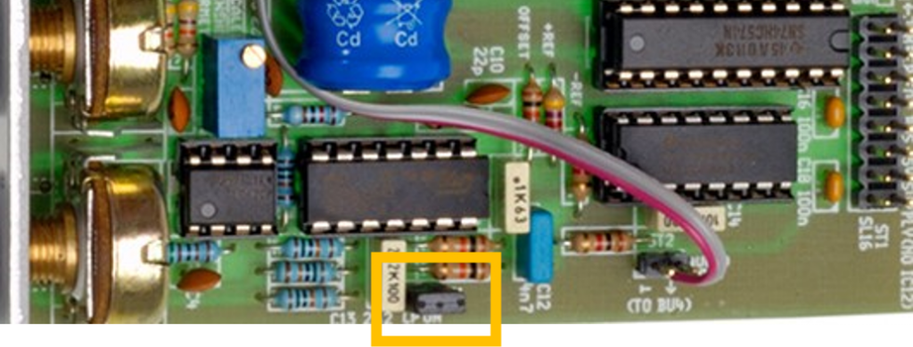
Possible weak point: storage battery
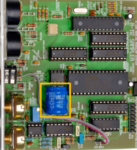
The module uses a small battery to preserve the contents of sample memory even when the A-100 system is turned off. Unfortunately, this battery does not have an unlimited service life and must be checked regularly (at least every 2 years) and replaced if necessary. Small soldering work is required for replacement in order to detach the leads of the battery from the circuit board or to attach them back to the circuit board.
With the A-112, this is a 3.6V battery measuring 10mm x 20mm (e.g. GP 3GP-60 or Varta 3/V80H).
Caution: A “leaking” battery can cause serious damage to the A-112 or modules installed underneath! Therefore, check every 2 years whether electrolyte liquid is leaking and whether the voltage is still at least 90% of the 3.6V. First remove the module completely from the housing and completely disconnect it from the power supply.
Configuration via the board
Bypassing the internal filter
The sampling frequency of the digital converter is – especially at lower sampling frequencies – an interference signal that is eliminated in the A-112 by an integrated low-pass filter. If you want to replace this filter with a higher quality one, the internal circuitry can be bypassed by removing jumper J1. Instead, you can use a steep-edged A-108 48dB filter, for example, which is also recommended for BBDs that have a very similar problem.
Sound examples
-
A-112 / Simple Recording and Playback
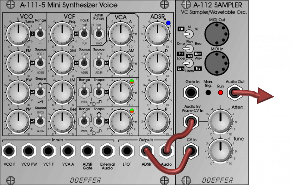
The source material is an A-111-5 Mini Synthesizer Voice controlled by an A-155 / A-154 Sequencer and A-156 Quantizer. The sequencer controller is set to “One Shot” and an A-164-1 Manual Gate starts the sequencer and recording of the A-112.
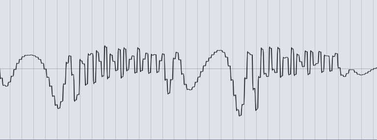
In order to be able to record the small sequence completely with the sampler, the sampling frequency is set to about 6 with the “Tune” control.
Original signal. A-112 recording at original speed. Record at different playback speeds – “Tune” controls at 10, 7, 4 and 1. The oscilloscope clearly shows the rasterization of the (slowed down) recording in the A-112:
-
A-112 / Wavetable Oscillator
In this sound sample, the A-112 is used as a wavetable oscillator. The entire content of sample memory S1 or S2 is not played back, but a 256-byte memory area that is repeated over and over again. Any such “wave” can be selected from the memory via a control voltage at the “Audio In / Wave-CV In” input. This selection can also be changed while playing, so you can move “forward and backward” or in jumps in the sample memory.
The source material is a small pre-recorded sequence from an A-111-5 Mini Synthesizer. The operating mode of the sampler is set to “Wave” with the lower switch. An A-118-2 Noise / Random Generator, whose S&H unit is clocked by an A-146 LFO, is used to modulate the pitch and the wave. The LFO also serves as a gate for playing the A-112. The “RND” output on the A-118-2 modulates the wavetable with its slow random voltage. The S&H output modulates the pitch/playback speed in the A-112.
First, the modulation of the pitch and the wavetable in the A-112 are minimal (“Level” control on the A-118-2 to 0, as well as the attenuator for “Audio In / Wave-CV In”). Then the “level” and thus the random modulation of the pitch of the sampler is slowly increased – at first we always hear the same wave from the recording.
From about 1 minute, the selection of the wave to be played is also modulated. In the following, the parameters of the random generator (proportion of “blue noise” / “red noise”, speed and level) are also changed until the modulation moves into extreme ranges from about 2:45”. At the end, the modulations are reduced again and the sampling speed in the sampler is reduced to a minimum.
Wavetable Oscillator. -
A-112 / Effects
For the sound examples of the A-112 as an effects device, we use an A-111-5 mini synthesizer as the sound source, which is controlled by an A-155 / A-154 sequencer. Two A-112 are configured as effects and distributed to the far right and left in the panorama, the original signal is in the middle. Some reverb from the DAW.
We start with the two A-112 in Pitch Shift mode, the two “Tune” controls are initially at maximum and are slowly regulated down manually and then back to maximum.
Pitch Shift. Then we switch to Delay mode. Again, we start with the “Tune” controls at maximum, slowly reduce to minimum and back.
Delay. Finally, the Reverse Delay mode is selected and again we start at the maximum “tune”, slowly going to the minimum and back to the maximum.
Reverse Delay.
Technical specifications
| Width | 10 HP |
| Depth | 100 mm |
| Power requirements | 50 mA (+12V) / -20 mA (-12V) |