The Bit Modifier / Bit Cruncher is one of the digital modules that can be modulated with analog control voltages. The module is based on a 12-bit converter, which fits quite well for the intended “Lo-Fi” effects.
Simply put, the module performs some purely mathematical operations after converting the audio signals into digital information and then converts the result back into analog audio signals.
User interface
Inputs:

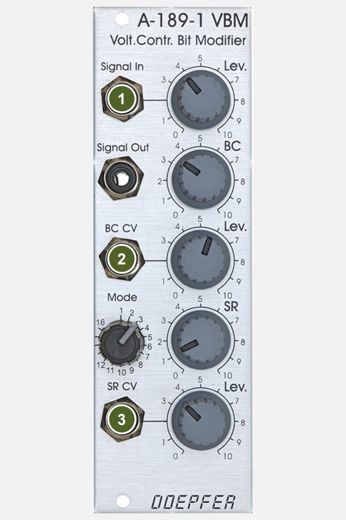
- Signal In: Audio input.
- BC CV: Control voltage input for modulating the Bitcruncher functions – depending on the selected mode.
- SR CV: Control voltage input for modulating the “sampling rate”, i.e. the resolution of the converter.
Outputs:

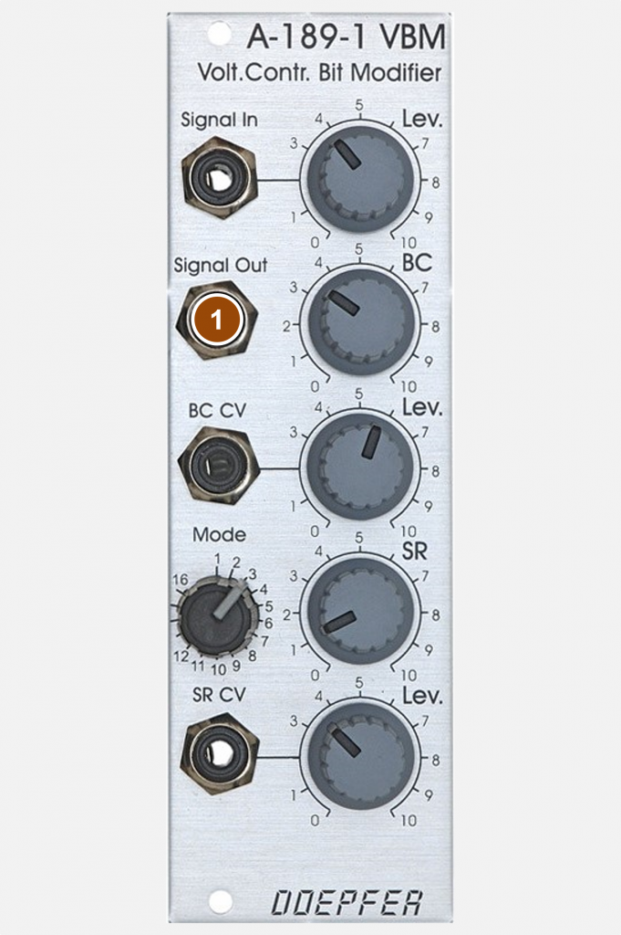
- Signal Out: Audio output.
Controls:

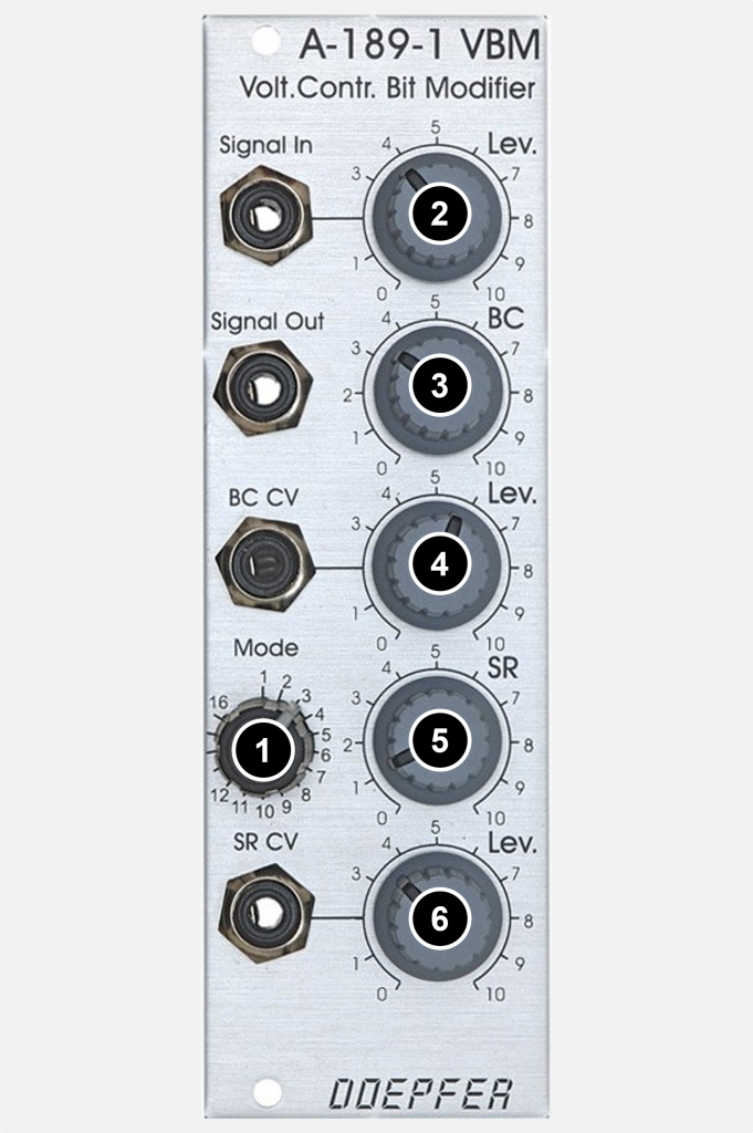
- Mode: Rotary switch to select the desired mode for manipulating the digitized audio data. Details on each mode are described in the table below.
- Lev.: Attenuator for the “Signal In” audio input.
- BC: Manual controller for the respective Bitcruncher function – depending on the selected mode.
- Lev.: Attenuator for the “BC CV” control voltage input.
- SR: Manual controller for the “Sampling Rate”.
- Lev.: Attenuator for the control voltage input “SR CV”.
Some math
The module provides 16 different mathematical functions via the “Mode” switch that can be applied to the digitized audio material:
| Nr. | Function | Comment |
|---|---|---|
| 1 | Reducing the number of bits (bit crushing) | The number of bits is set via BC, so that the resolution of the amplitudes (and thus also the overtone structures) can be reduced from the original 12 bits to an extremely low one. |
| 2 | AND | The bits of the value of BC are combined with the bits of the digitized audio signal via a logical AND. |
| 3 | OR | Like function 2, but with a logical OR link. |
| 4 | XOR (exclusive OR) | Like function 2, but with a logical XOR operation. |
| 5 | Bit shift to the right | The bits of the digitized audio signal (e.g. 111101100111) are shifted to the right by a number of places. The number of digits is defined via BC. |
| 6 | Bit shift to the left | Like function 5, but with the bits shifted to the left. |
| 7 | Multiplication | The digitized audio signal is multiplied by BC. |
| 8 | Comparison & Complement | If the digitized audio signal is greater than BC, then the complement (all 1’s become 0’s and vice versa) is output, otherwise the original signal. |
| 9 | Comparison & Absolute Value | As function 8, but with the absolute value of the digitized audio signal instead of the complement. |
| 10 | Addition | The value of BC is added to the digitized audio signal, if the maximum value is exceeded, it is severely cut off (digital clipping). |
| 11 | Addition with the BC Swap | Like function 10, but with only half a byte (4 bits) of BC. |
| 12 | Short Delay 1 with dynamic normalization | The amount of memory for the delay is controlled with BC. |
| 13 | Short Delay 2 | Like function 12, but with a different delay time / feedback. |
| 14 | Short Delay 3 | Like function 12, but with a different delay time / feedback. |
| 15 | Short Delay 4 | Like function 12, but with a different delay time / feedback. |
| 16 | FIR Filter | BC controls the filter coefficient. |
Sound examples
-
A-189-1 / All Bitcruncher modes
The following sound examples introduce all 16 modes of the A-189-1. In each example I start with the highest sampling rate, after about 30 seconds we reach the lowest sampling rate. Meanwhile, two independent triangle LFOs modulate the two parameters of the Bitcruncher.
The starting material is three A-110-1 VCOs, the mixture of which is filtered with an A-108 and amplified by an A-132-3 VCA. The sound generation is controlled by an A-155 sequencer.
Mode 1: Reduction of the number of bits (bit crushing). Mode 2: AND. Mode 3: OR. Mode 4: XOR (exclusive OR). Mode 5: Bit shift to the right. Mode 6: Bit shift to the left. Mode 7: Multiplication. Mode 8: Comparison & Complement. Mode 9: Comparison & Absolute Value. Mode 10: Addition. Mode 11: Addition with the BC Swap. Mode 12: Short Delay 1 with Dynamic Normalization. Mode 13: Short Delay 2. Mode 14: Short Delay 3. Mode 15: Short Delay 4. Mode 16: FIR Filter.
Technical specifications
| Width | 8 HP |
| Depth | 60 mm |
| Power requirements | 50 mA (+12V) / -20 mA (-12V) |
