A Lowpass Gate (LPG) is an odd device. It uses a vactrol circuit and couples a low pass filter to an amplifier (VCA).
Then why not just use a filter and an amplifier separately? The LPG can be switched between VCF, VCA and the combination VCF / VCA! In addition, the module is built with a vactrol and sounds – also as a VCA – different than conventional filters or amplifiers. The inertia of the vactrols leads to a “natural” decay behavior of the VCA.
Incidentally, the module is one of a series of modules that are clearly inspired by concepts by the American synthesizer pioneer Don Buchla (without wanting to replace a Buchla system): The random number generators A-149-1 and A-149-2 are further examples.
Buchla synthesizers differ significantly in the complexity of the modules, but also in the user interface, from the more keyboard-oriented models from Moog or ARP.
User interface
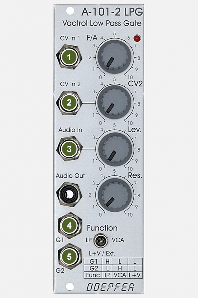
Inputs:

- CV In 1: Control voltage input for the cutoff-frequency (without attenuator).
- CV In 2: Control voltage input for the cutoff-frequency (with attenuator).
- Audio In: Audio input.
- G1: Gate input for switching the filter modes. If a gate signal (e.g. from a sequencer or a keyboard) is present here, it switches from VCF / VCA to VCF (lowpass filter mode “LP”) or from VCA to VCA / VCF (depending on the mode selected with the switch).
- G2: Gate input for switching the filter modes. If a gate signal (e.g. from a sequencer or a keyboard) is present here, it switches from VCF / VCA to VCA or from VCF to VCF / VCA (depending on the mode selected with the switch).
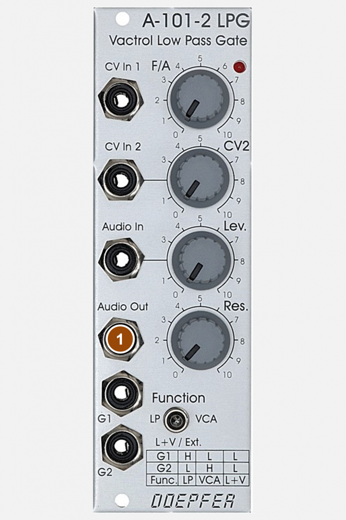
Outputs:

- Audio Out: Audio output of the module.
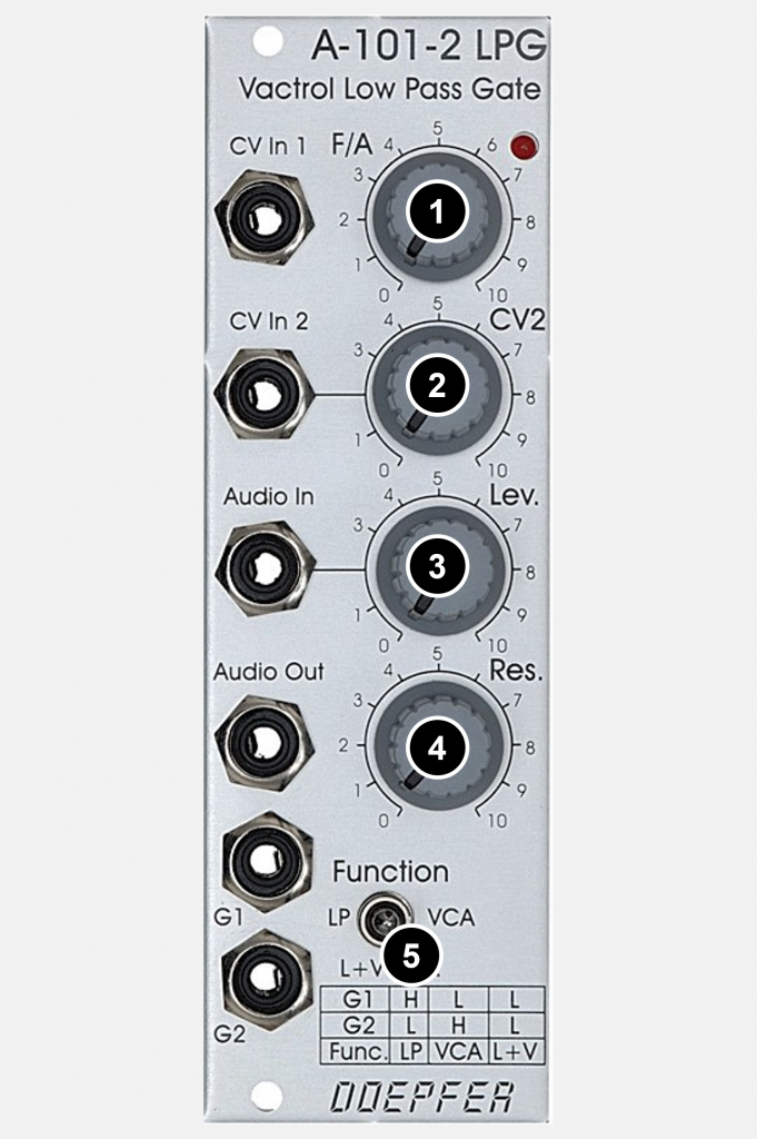
Controls:

- F/A: Controller for the cutoff-frequency or for the amplitude of the amplifier – depending on the selected mode. With the combination VCF / VCA, both the cutoff-frequency and the amplitude are controlled (from quiet and heavily filtered frequency response to loud and open filter).
- CV2: Attenuator for the control voltage input “CV In 2” for the cutoff-frequency.
- Lev.: Attenuator for the audio input.
- Res.: Controller for the resonance of the filter (up to self-oscillation in LP mode). A kind of “resonance” can also be controlled in the “VCA” mode; it affects the ringing with very short envelope curves in the “CV In 1” or “CV In 2” input.
- Function: Manual switch for the operating modes of the filter: VCF, combination of VCF and VCA, VCA.
Possible uses
Switching via sequencer
The A-101-2 can be easily switched between the operating modes using a sequencer or random generator.

Self-oscillation only in LP mode
The filter is only capable of self-oscillation in the LP operating mode. The filter sound changes audibly when switching between “LP” and “LP / VCA”.
Sound examples
-
A-101-2 / Sequence with LPG mode switching
As in many other demos, I use three A-110-1 VCOs (all sawtooth, one VCO an octave lower) controlled by an A-155/A-156 sequencer. The mix of the three VCOs is patched to the A-101-2 LPG input. The LPG modes are switched by a random module (A-149-2) synchronized with the sequencer. The filter cutoff-frequency and/or gain is controlled by another random module (A-149-1) and an A-140 ADSR. Finally, the audio signal goes into an A-132-3 VCA, which isn’t strictly necessary as our A-101-2 can also work as a VCA, but the two VCAs react quite differently and show some interesting “behaviours”.
We start with no filter resonance, a moderate LPG input level, and neither the LPG nor the A-132-3 are modulated by the A-140 ADSR. Then the ADSR modulation on the LPG is increased. Then (at 0:50) the filter resonance is increased, as is the input level (resulting in slight distortion in the LPG). After that, the A-132-3 is modulated by the A-140 (instead of just constantly amplifying everything). Finally, there are a few changes to the modulation depth and resonance.
Sequence with random switching of LPG modes.
Technical specifications
| Width | 8 HP |
| Depth | 50 mm |
| Power requirements | 20 mA (+12V) / -20 mA (-12V) |
