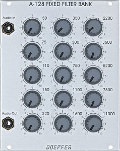
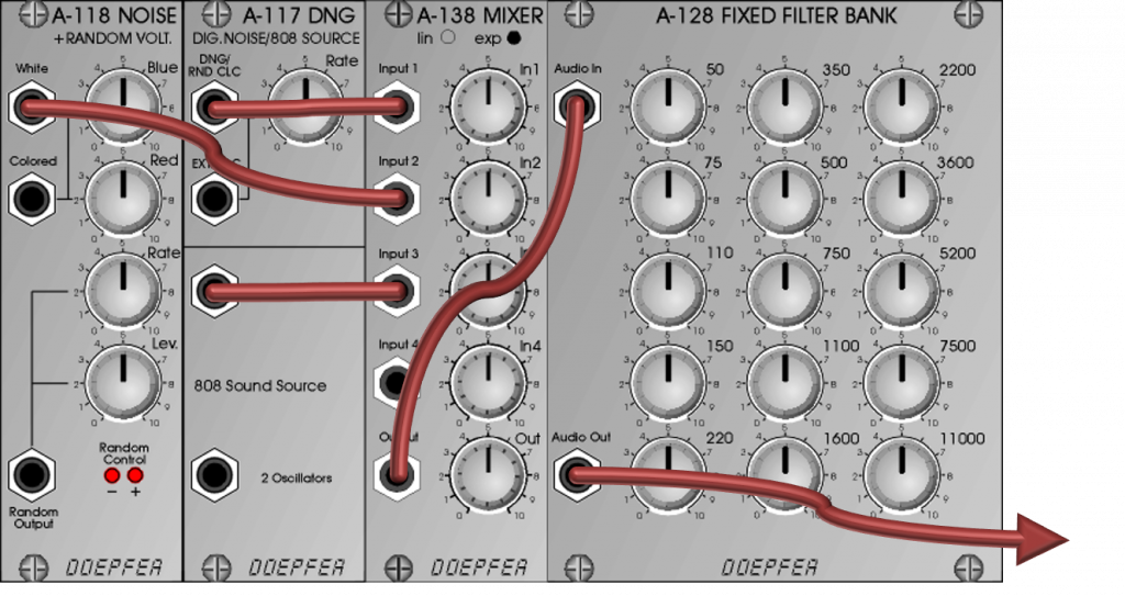
A fixed filter bank is a “distant relative” of the graphic equalizer. We find 15 frequency bands whose volume is individually adjustable. Behind this are 15 parallel bandpass filters (with 1/2 octave bandwidth), whose output signals can be faded in.
In contrast to a graphic equalizer, the fixed filter bank does not have a linear “neutral position”: If all controls are at 0, then no signal at all reaches the output socket, if all controls are at 5 or 10, then the frequency response is by no means linear, but rather has many notches due to the narrow filter bands. In return, very drastic sound changes can be implemented with the filter bank. Unfortunately, modulation via control voltage is not possible.
The role model? An “ancestor” of the module can perhaps be seen in the Moog 914 module, which, however, also had a high-pass and a low-pass filter. The frequencies of the 12 fixed frequency bands were also slightly different from the A-128. So it’s more of a “distant relative”.
User interface
Inputs:
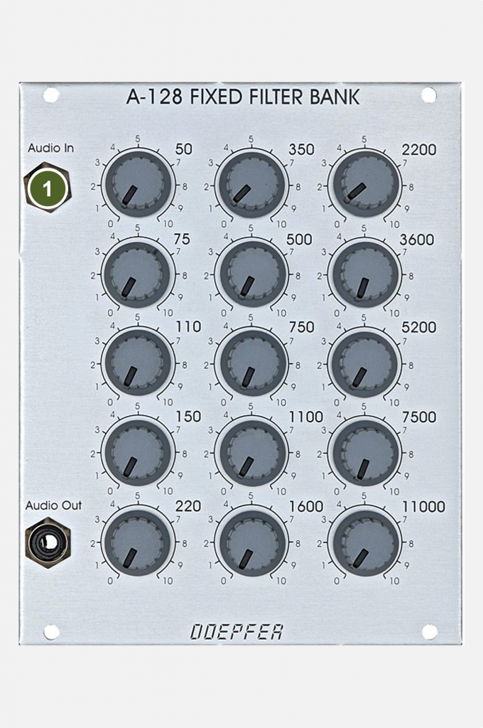
- Audio In: Audio input.
Outputs:
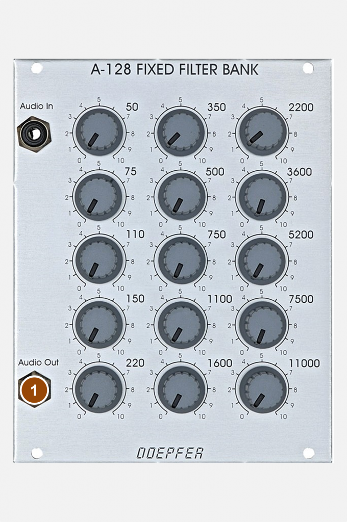
- Audio Out: Audio output for the filtered signal.
Controls:
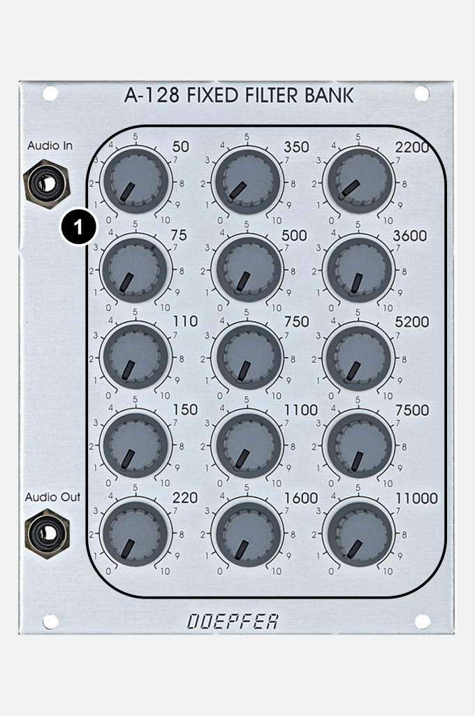
- Volume controls (for each of the 15 bands) to adjust the levels of the frequency bands.
Shaded noise
The filter can be used to create very specific “shades” of noise, etc. A mixture of the original and filtered signal is recommended to emphasize frequencies.
When all controls are set to “0”, nothing will be heard. From there, try to build your desired sound.
Modification – single outputs
The possibility of individual exits is described on the Doepfer website. This can either be done as a do-it-yourself project or custom-made by Doepfer. Here, e.g. with 15 VCAs, a voltage control of the components of the individual frequency bands would also be conceivable.
For each of the three filter boards of the module there are 5 tapping points (each either before or after the attenuator of the frequency band), which can be connected to sockets for the individual outputs. Due to the three circuit boards (for 5 filters each) lying on top of each other, however, it is quite a fiddly job and with 15 VCAs it is not a very inexpensive modification either.
Relatives and alternatives
Instead of the complex modification with individual outputs and more than a dozen VCAs, the use of one or more A-127 Triple Resonance Filters is worth considering: The A-127 does not cut out individual frequency bands, but only emphasizes individual frequencies. But they can be tuned variably and can even be controlled via external control voltages, the individual outputs are already integrated.
The A-104 formant filter is another possible alternative to the A-128. We only have four bandpass filters (each switchable to low-pass), but these can be tuned – purely manually – and can therefore also be used very nuanced for the generation of more complex formants.
If you are looking for a voltage-controlled alternative for the fixed filter bank: Take a closer look at the A-129 / 1&2 Vocoder – unfortunately no longer available. It consists of 15 amplitude-controlled fixed-frequency filters (13 band-pass filters, one high- and one low-pass filter) with very complex options if you use the slew limiters (can be switched separately for each band) together with the control unit. However, this complexity and the associated “cable clutter” are also the biggest shortcoming of the vocoder when used quickly in practice.
Sound examples
-
A-128 / Filtered noise
A “typical” application of the fixed filter bank A-128 is the specific coloring of noise. In our examples, white noise from an A-118-1 is used. First the unfiltered input signal:
White noise from an A-118. The following two examples show how noise is processed by the fixed filter bank. First I start with the 11,000 Hz filter (completely open, all other bands are set to 0), then the next filter band (7,500 Hz) is set and the 11,000 Hz band faded out. I continue filter by filter down to the 50 Hz band:
All filter bands from top to bottom, white noise as input signal. In the second example, I use an arbitrary mix of filter bands, which is further changed manually over the course of the process. You always hear a mix of multiple filter bands fading in and out:
More or less random compilation of the filter bands, which are manually faded in and out. Finally, the “random” fading in and out of different filter bands again, but this time with a simple sequence from an A-111-5 mini synthesizer:
“Random” fading in and out of the filter bands with a sequence from the A-111-5.
Technical specifications
| Width | 20 HP |
| Depth | 60 mm |
| Power requirements | 20 mA (+12V) / -20 mA (-12V) |