The module is no longer in production.
The A-172 maximum/minimum selector leaves many “modularists” at a loss at first.
A module that selects and makes available both the maximum and the minimum voltage from up to four input signals may appear too “mathematical” or intricate.
In fact, the module is a surprisingly easy-to-use tool for control voltages and audio signals.
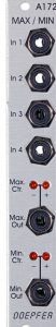
User interface
Inputs:
Outputs:
MAX / MIN for control voltages
Complex control voltages
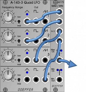
A highly complex control voltage that is less “predictable” than a mere mixture of the voltages can be obtained very easily from a few LFO signals that are not in sync with one another.
Limitation of random tone sequences
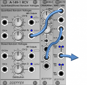
For melodies from random generators, the pitch range of a random tone sequence can be very well limited upwards or downwards by introducing a constant voltage from an offset generator in addition to the control voltage responsible for the melody. Then the “Max. Out” is used for a lower limit (the constant control voltage from the offset generator can no longer be undercut) or the “Min. Out” for an upper limit.
Parallel use of max and min
Even a sine wave processed together with a manually controlled offset voltage produces interesting counter-propagating patterns well suited for stereo processing.
If another signal – e.g. an envelope curve – is added, you get results that are hardly achievable in other ways. The envelope should have a negative offset of about 4V.
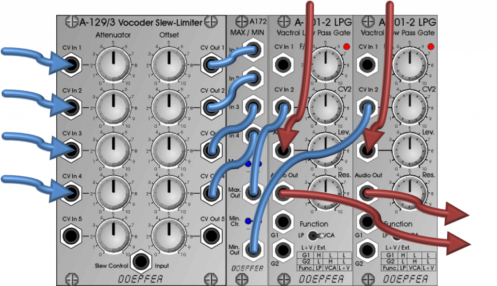
Fine adjustment with the A-129 / 3
An A-129 / 3 Slew Limiter / Attenuator / Offset Generator can be connected upstream of the module for control voltages.
The A-172 Maximum / Minimum Selector as waveshaper
The A-172 is not a waveshaper per se, but primarily a tool for “mathematical” processing of voltages: the maximum or minimum is selected from the signals of the four inputs and then sent to the two outputs. This works not only with control voltages, but also with audio material!
Soft clipping
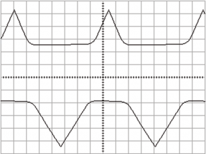
If you use an audio signal and a constant voltage (e.g. from an offset module) as input signals, you have already built an interesting audio tool:
The “minimum” output will reproduce the audio signal as long as it is “lower” (i.e. less voltage) than the constant voltage.
When it is exceeded, the constant voltage is output – that’s what a clipper does! Compared to other clippers, however, the A-172 works relatively “softly”.
Two audio signals as input
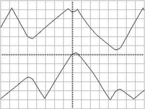
Can it be a little more complex? Instead of an audio signal and a constant voltage, use two or more audio signals. Compare what happens when the audio signals are in sync with each other (e.g. via oscillator sync) or when they show slight / stronger beats. In the latter case, you get very moving sounds with unusual frequency boosts and cancellations.
Distribute the two outputs “Max” and “Min” in the stereo panorama, the result sounds very “broad” and can hardly be achieved with other techniques.
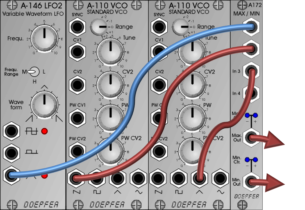
The following patch could be used for such “stereo broadening” with modulation by an LFO:
Note: The A-186-1 Gate / Trigger Combiner is also able to work as a Maximum Selector. In addition to audio signals, constant control voltages or voltages from LFOs can of course also be “integrated”.
Sound examples
Here we use two A-110-1 VCOs: From the first VCO the sawtooth oscillation, from the second VCO the pulse/square wave oscillation, both directly into the Max / Min. The two “Max” and “Min” outputs are distributed in the stereo image. We start with 100% pulse width and slowly reduce it manually. After that, the two VCOs are slightly detuned to each other.
Alternatives
Unfortunately, the module is no longer manufactured. A successor is also not in sight. Are there at least similar solutions?
The A-116 VC Waveform Processor offers an asymmetrical clipping that can be modulated by the control voltage, but which on the one hand cuts off “harder” and thus sounds completely different, on the other hand it only corresponds to the “min” part of the A-172. The original input signal can be added to the signal processed in this way, or added inverted.
The A-136 Distortion / Waveshaper offers a little more. It can truncate a waveform separately at both the top and bottom edges. This also works via control voltages, which then correspond to the second input of the A-172, for example. However, the A-136 does not output separately for upper and lower clipping.
At the end of the day, none of the modules offer the possibility of mutually influencing up to four audio and/or control voltage signals.
Technical specifications
| Width | 4 HP |
| Depth | 30 mm |
| Power requirements | 10 mA (+12V) / -10 mA (-12V) |