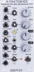
Compared to the A-110-4 Quadrature Thru Zero VCO, the A-110-6 has one more thing on top: We are not dealing with a sine core, but with a trapezoid core. This is a unique design that first creates a trapezoidal waveform, as well as a 90 degree phase-shifted trapezoid (the equivalents of the A-110-4‘s sine and cosine, so to speak). In addition, the conventional waveforms triangle, sine, square and sawtooth can be derived from the trapezoid – each with a 90 degree phase-shifted “cosine” variant. Thru-zero modulations are possible as with the A-110-4. The A-110-6 is currently Doepfer’s most complex single VCO.
The area of application is naturally similar to that of the A-110-4, but allows a richer spectrum of sounds, especially with FM, thanks to the additional waveforms. In addition, the A-110-6 is significantly less sensitive to modulator DC offsets during linear frequency modulation.
Like the A-110-1 or A-110-2, the module is equipped with a heating element for the temperature-sensitive components, so it remains tuning-stable even when the ambient temperature changes.
User interface
Inputs:
System bus: As with the A-110-1 or A-111-1, the pitch of the A-110-6 can be controlled via a voltage on the system bus. The system bus can be addressed with an A-185-1 or A-185-2 or, if necessary, deactivated with a jumper on the circuit board.
As with all VCOs with CV control via the bus, you should deactivate this option if you are not using it: Otherwise, the open lines could work as “antennas” and pick up interference signals.
- 1 V/Oct: Exponential control voltage input. This input corresponds to the main control inputs of other VCOs and can be used with a CV keyboard or a sequencer, for example.
- XFM: This control input also works exponentially, but has an attenuator (“XFM” control) with which the control voltage applied here can be regulated, e.g. for a vibrato from the control voltage of an LFO.
- LFM: In contrast to the other two control inputs, the “LFM” input works linearly, so it is ideally suited for linear frequency modulation, e.g. with a second A-110-6.
Outputs:
- TRISIN: Triangle.
- TRICOS: Triangle, 90° out of phase.
- SINE: Sine.
- COSINE: Sine, 90° out of phase.
- RECSIN: Square.
- RECSIN: Square, 90° out of phase.
- SAWSIN: Sawtooth.
- SAWCOS: Sawtooth, 90° out of phase.
- TRASIN: Trapezoid.
- TRACOS: Trapezoid, 90° out of phase.
Controls:
- VCO / LFO: Switch between VCO or LFO mode (frequency range reduced by a factor of approx. 100)
- XTune: This control is used to set the basic frequency of the oscillator. The control range is enormous, so fine tuning requires a little more sensitivity than, for example, with the A-111, which has two controls for coarse and fine tuning in addition to an octave selector switch.
- XFM: Attenuator for the exponential control voltage input “XFM”.
- LFrq: A linear controller for the frequency of the oscillator, which – in contrast to the “XTune” controller – can also go through the “zero point”: The frequency of the oscillator reaches 0 Hz around the middle of the control position and below that the frequency increases again, but with the inverted phase of the audio signal.
- LFM: Attenuator for the linear control voltage input “LFM”.
Configuration on board
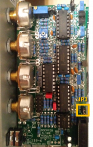
In addition to many trimming potentiometers, the board offers the option of either accessing a control voltage in the A-100 bus or interrupting this connection. Control voltages from the bus are always added to control voltages at the “1V/Oct” input, e.g. to transpose the oscillator via the bus while it is being controlled by a sequencer through the 1V/Oct socket.
Jumper 3 connects the module to the bus (inserted) or disconnects (jumper removed). The jumper itself is somewhat hidden behind a ribbon cable that connects the two circuit boards.
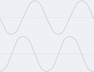
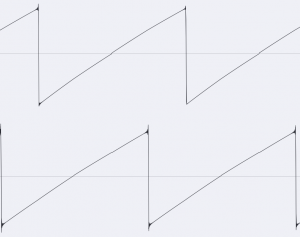
How do the waveforms look like?
A quadrature oscillator with no fewer than 5 waveforms is technically quite complex. On the oscilloscope images, we see the normal output at the bottom and the “cosine” output that is phase-shifted by 90° above it.


Linear frequency modulation
With its very special possibilities, the A-110-6 is certainly not a “bread and butter” VCO. For such a bread and butter VCO one would also expect features like an octave selector switch or pulse width modulation.
However, the module becomes interesting with the linear frequency modulation, which is also possible here in the negative range, so that the original oscillation form is inverted. Of course, this is not yet a super-exact DX7, but the “organic” behavior of the A-110-6 in particular, together with the unusual range of basic waveforms, offers a lot of scope for sound experiments.
Sound examples
-
A-110-6 / Linear frequency modulation
In the following sound examples, the A-110-6 is modulated by an A-110-4 (LFM input). The A-110-6 is controlled by a simple A-155 sequence, the trapezoidal output goes into an A-132-3 VCA (linear) controlled by an A-140 envelope.
We start with the pure trapezoid signal without FM. The modulation intensity is slowly faded in, while the frequency of the A-110-4 is changed manually. Finally, the A-110-4 also gets linear frequency modulation with a second A-110-4, here too I adjust the frequencies of the two A-110-4 VCOs manually.
Linear frequency modulation with one and finally cascaded with a second A-110-4. Due to the fixed frequency of the modulation VCOs compared to the A-110-6, the sound changes with each step of the sequence. In a next step, I use the same setup, but now also connect the two A-110-4 to the sequencer (1V/Oct input). In order to create different tones, I again manually adjust the tuning of the two A-110-4 VCOs in the course of the example. A worthwhile field here would be defined intervals between the oscillators, in the examples I just “screwed around blindly” without e.g. setting the tuning precisely with a tuner.
Linear frequency modulation with two cascaded A-110-4, also controlled by the sequencer. Finally, I route the output of the A-110-4, which directly modulates the A-110-6, through an A-101-2 lowpass gate controlled by a simple AR envelope from an A-143-1. This gives the frequency modulation its own envelope, which I – like the tuning of the A-110-4 VCOs – also change manually in the course of the example. The lowpass gate is initially in “LP+VCA” mode. Towards the end (from about 2:30) I switch to the pure filter when the filter resonance is high, in order to use the self-resonance as an additional modulation source for the A-110-6.
Linear FM with two cascaded A-110-4s, also controlled by the sequencer and influenced in amplitude/timbre by a lowpass gate. Finally, a series of sound examples with the same setup as before (sequencer controls all VCOs, the two A-110-4 are filtered by an LPG), but with the A-110-6 setting the frequency modulation much more subtly to show the effect on the various waveforms of the A-110-6:
Triangle from the A-110-6. Sine from the A-110-6. Rectangle from the A-110-6. Sawtooth from the A-110-6. Trapezoid from the A-110-6. -
A-110-4, A-110-6, A-133-2 / Modulation in the polarizer
In this sound example, the two 90 degree phase-shifted sawtooth outputs of the A-110-6 are modulated in an A-133-2 VC polarizer by the sine and cosine outputs of an A-110-4. In principle, this is an amplitude modulation that changes phase when the control voltage is negative (ring modulator principle). We hear the two outputs of the polarizer distributed to the stereo channels. The tuning of the two VCOs is controlled by hand.
A-110-6 in the VC polarizer, modulated by an A-110-4. -
A-110-4, A-110-6, A-172 / Phase shifted in the Max/Min Selector
In this example we use an A-110-6 and an A-110-4 with their sine outputs each phase-shifted by 90 degrees. The aim is the four input signals of an A-172 Max/Min Selector. The two outputs for Max and Min are distributed over the two stereo channels. My two A-110-4s are from an earlier series with a significantly lower output level than the A-110-6, which leads to interesting side effects here. The tuning of the two VCOs is again controlled by hand.
A-110-6 in the Max/Min, together with an A-110-4.
Technical specifications
| Width | 12 HP |
| Depth | 55 mm |
| Power requirements | 80 mA (+12V) / -70 mA (-12V) |