The A-133-2 is a dual voltage controlled polarizer, meaning its input signals (audio or control voltages) can be amplified like a traditional VCA. With a negative control voltage or a corresponding manual setting, the input signals are amplified in inverted form.
An input, a control voltage input, an output, as well as a manual controller for amplification / inverted amplification and an attenuator for the control voltage are available for each sub-module.
First of all, that is exactly what the A-133 also offers, which is with its 8 HP exactly twice as wide as the “Slim Line” A-133-2. On the one hand, this makes the A-133 much more convenient to handle, but it also takes up more of the always scarce space in the case.
In addition, the A-133-2 has another control voltage input per sub-module: Here the control voltage itself can be modulated once more, but this time only conventionally via a VCA and not another polarizer.
Another not unimportant difference is the amplification factor: while the original A-133 can amplify positively or inverted by a factor of up to 2.5, only a positive or inverted amplification up to a factor of 1 is possible with the A-133-2 (as with most common VCAs). “Real amplifiers” are rare, although they have their justification, but if the voltages are amplified too much (e.g. through several “real amplifiers” in a row in a complex patch) you sometimes end up with voltages that overwhelm one or the other module or could lead to damage.
User interface
Inputs:
Outputs:
Controls:
Differences to the A-133
Even if all settings are the same, there are still sonic differences between the A-133 and the A-133-2, especially when used as a ring modulator. For ring modulation, both the input signal and the polarization control voltage are in audio frequency.
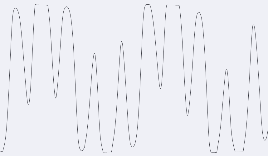
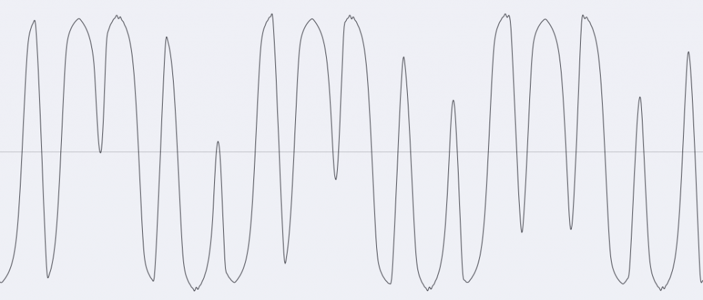
The reason for the differences is mainly the significantly higher amplification factor of the older module. If both the input signal and the control voltage have a comparatively high level, hard clipping occurs with the A-133, but not with the A-133-2:
Sound examples
In the first sound example, two A-143-9 VCLFO/VCOs are used as input signal or modulation source. For a “classic” ring modulator use, the “Man.” control is in the middle position and the “CV” attenuator for the control voltage input is at maximum. The frequencies of the VCOs are controlled simultaneously via an A-174-1 joystick.
In the next example, the two A-143-9 are used again, this time the “Man.” control is changed during recording and the level or polarity of one of the two signals is additionally manipulated. The frequencies of the two VCOs remain constant.
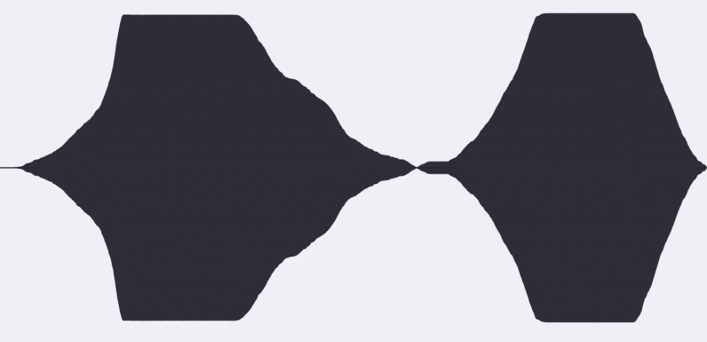
In the next example, only one input signal from an A-143-9 is used without modulation. The “Man.” control is moved from maximum to center (i.e., cutting out the signal as much as possible) and then to minimum (i.e., outputting the signal inverted) and back to center. You can hear the input signal fade out almost completely, as the waveform images of the recording show.

In the next example, two A-110-1 VCOs with their sawtooth outputs are used as input signal and polarization control voltage. The overtone-rich spectra lead to significantly more complex sound changes compared to the sine signals of the previous examples. After a while the two VCOs have been tuned to almost the same frequencies, and from about 0:22 the modulation input is also used with an A-110-6 (sawtooth output) to modulate the ring modulation.
The next sound example does not use ring modulation (with its inversion of the signal when the control voltage is negative), but simple amplitude modulation. For this purpose, an A-110-1 VCO (sawtooth output) is used as the input signal again, there is no external control voltage, but an A-110-6 VCO (also sawtooth output) modulates the “Man.” control position via the “Mod” input. The strength of the modulation is controlled by an interposed A-183-1. It uses the A-110-6‘s “Thru Zero” capability to switch from falling to rising sawtooth.
In the last example, both sub-modules of the A-133-2 are used for a stereo application. Two A-143-9 VCLFO/VCOs serve as input signals or control voltages for the polarization. The “cosine” output is the input signal, the sine output of the other A-143-9 is the modulation source for the polarization.
Technical specifications
| Width | 4 HP |
| Depth | 40 mm |
| Power requirements | 20 mA (+12V) / -20 mA (-12V) |