Like the A-117 Digital Noise, the A-118-1 is also a random noise generator. However, it does not work with feedback shift registers, but with the “natural” noise of transistors and thus generates a very typical “synthesizer” noise.
Dieter Döpfer once explained to me that due to the component tolerances of these transistors, each A-118-1 sounds a little different – interesting!
Many synthesizers and noise modules try to express the noise characteristics with colors. A “white” noise theoretically (but rarely in real systems) contains all frequency components in the same amplitude. In addition, pre-filtered noise is offered in different color variations: “Red” noise, which has less treble components, “blue” noise, which has less bass components.
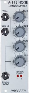
User interface
Outputs:
- White outputs the white noise. Adjusting the controls has no effect on the sound.
- Colored outputs a colored noise, in which the low and high frequency components can be adjusted using the “Red” and “Blue” controls.
- Random Output emits a random voltage – with frequencies mostly below the audible limit. Two control LEDs show the current voltage. The shape and course of the random voltage are influenced by “Rate” and “Level” (see below), but also by the “Red” and “Blue” controls, since the voltage is derived from the colored noise.
Controls:
- Blue controls the amount of high frequencies at the Colored output.
- Red controls the amount of low frequencies at the “Colored” output.
- Rate controls the period of the random voltage at the “Random Output” output. Somewhat counterintuitive: 0=fast and 10=slow. Only at a low rate does the random voltage sound like typical noise, after which individual pulses become increasingly audible as clicks.
- Lev. controls the amplitude of the random voltage.
Overview
Like the A-117, which in addition to the noise also masters metallic cymbals and cowbell sounds à la TR 808, the A-118-1 has a very useful additional function as well: A randomly changing voltage with a comparatively low frequency. The speed of the changes and the amplitude are adjustable.
In addition to white noise, very variable colored noise can be generated with the A-118-1:

Possible uses
“Smoky” sounds
Noise is a wonderful addition to patches that are supposed to sound “slightly scratchy” or “smoky”. Snare drums or the percussive “attack” of other drum sounds are inconceivable without noise.
Noise as a modulation source
In addition to adding noise to the VCOs, there are other simple ways to “roughen” a sound with the A-118-1, for example by modulating the VCO pitch or the cutoff frequency of filters:
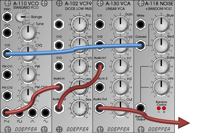
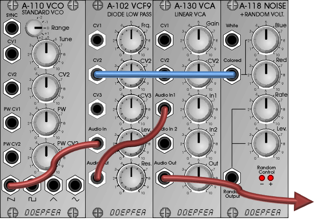
“Random Out” as noise source
Even if the random output is actually intended as a supplier of random control voltages, it can still provide a nice variant on the subject of “noise”:
The influence of “Blue” and “Red” on the random voltage has already been briefly mentioned in the description of the module’s outputs. The “Blue” control only provides an audible additional “skylight” on top of the noise at extremely small “Rate” settings, but from a “Rate” setting of around 1 it can be neglected. Even more so, the extent of “Red” affects what we hear. As the red component increases, the low-frequency noise begins to stutter and is repeatedly interrupted by impulses (clearly audible as clicks). If the “Rate” control is then turned up from 0, the clicks smooth out, the frequency spectrum becomes even lower overall, until finally a barely audible signal remains.
The noise from the random output is comparatively muted and soft, the influence of “Red” and “Blue” is slightly higher than with the normal “Colored” output:

Attention: Depending on the recording equipment, extremely low-frequency signals may also be recorded and can then lead to problems with mixing, compression, etc. of the recording. We don’t hear anything, but there is a signal that can possibly lead to distortion. If in doubt, make a test recording and check it graphically. Most recording programs offer such an option, whether there is still a “tone” of maybe 1-2 Hz.
Control voltages with the A-118-1
Both the A-117 and A-118-1 modules are not only practical sound generators for “noisy” sounds, but can also generate random control voltages. With the A-118-1 we get a randomly fluctuating voltage suitable for continuous control tasks.
Sound examples
-
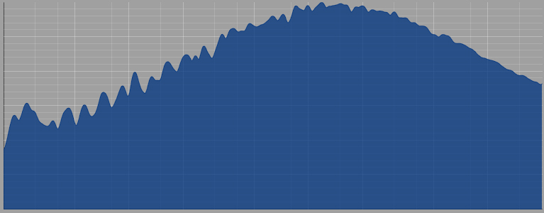
A-118-1 / White Noise
White noise from the A-118-1.
A-118-1 White Noise. -
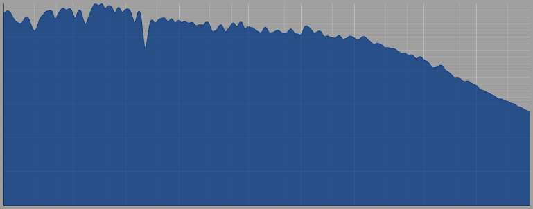
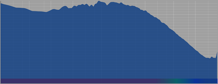
A-118-1 / Colored Noise
Colored noise (output “Colored”) from the A-118-1. First without red and blue noise, then the “blue” component is increased and then reduced back to 0, then the “red” component is increased and decreased, finally the “blue” and “red” noise are increased simultaneously and back to 0 for both :
A-118-1 Colored Noise. -
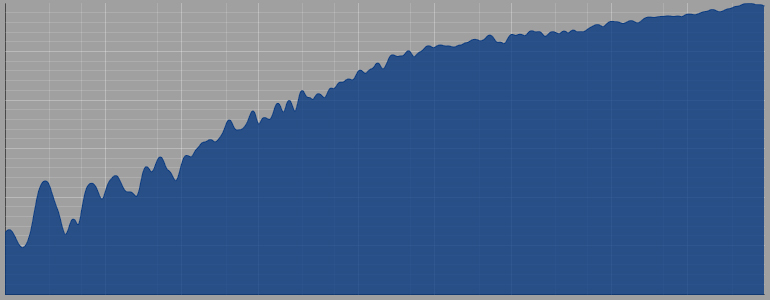
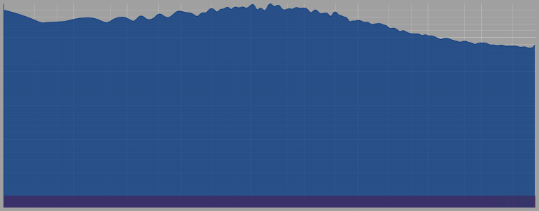
A-118-1 / Random Out
In this sound example, the “Random Output” of the A-118-1 is used as the sound source. The rate is initially set to “0”. We start without red and blue noise, then the “blue” component is increased and then reduced back to 0, then the “red” component is increased and decreased, and finally the “blue” and “red” noise are increased simultaneously. At the end, with maximum controllers for “Blue” and “Red”, the rate is increased a little (to about “1”) and at the end all controllers back to “0”:
A-118-1 Random Voltage. -
A-118-1, A-118-2 / Comparison of white and colored noise
Since the Slim Line Module A-118-2 can basically do everything that is possible with the A-118-1 and also has an S&H / T&H with half the rack space for a small additional charge, direct comparisons are interesting. With all of this, you should of course be aware that analog noise from transistors always involves a certain amount of scatter due to the components: Differences demonstrated here can be caused by different circuits (i.e. they can be REAL differences), but also simply because each A-118-x sounds slightly different than another A-118-x.
In the following we always have the A-118-1 on the left and the A-118-2 on the right. I try to keep the relevant knob positions the same as possible.
White noise: Yes, there are differences, the old A-118-1 (left) seems to have a little more low-frequency components than the new A-118-2 (right).
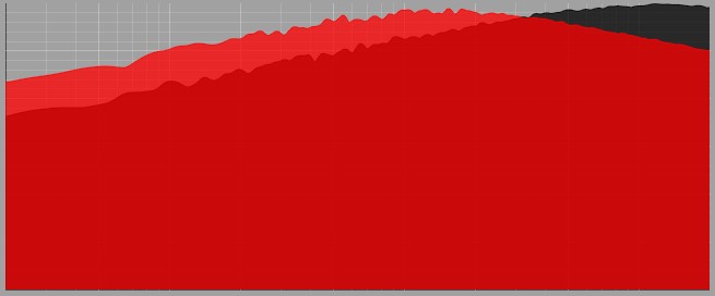
White Noise: Red = A-118-1, Black = A-118-2. White Noise. Left A-118-1, right A-118-2. Colored Noise: Here I try to regulate the blue noise (high-frequency components) from 0 to maximum for both noise generators at about the same time, back to 0, then the red noise also from 0 to maximum and back and finally both blue and red noise from 0 to maximum and back again. I beg your pardon here, as I probably didn’t move the controls completely in sync. In any case, the differences in sound are limited.
As with white noise, my A-118-1 seems to have a slight preference for lows over highs compared to my A-118-2, and to have slightly fewer high-frequency components.
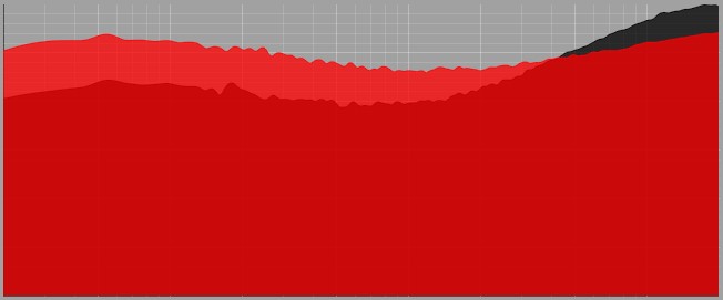
Colored noise (“Blue” and “Red” set to 10): Left A-118-1, right A-118-2. Colored noise: left A-118-1, right A-118-2. Overall, the two modules react very similarly. The differences can be caused by component tolerances, but also by fine-tuning the modules or small adjustments to the circuit design. In practice, however, both modules can be used in the same way.
Technical specifications
| Width | 8 HP |
| Depth | 40 mm |
| Power requirements | 20 mA (+12V) / -10 mA (-12V) |