“Processor” here does not mean a processor in a computer, but simply an (analog) circuit that can change waveforms.
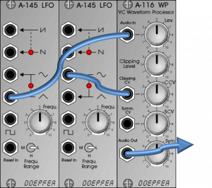
Here the input signal is processed by two parallel circuits, the results of which are then mixed together: a clipper, which cuts the input signal sharply above a threshold, and a polarizer/attenuator, which can both attenuate and invert the signal.
User interface
Inputs:
- Audio In: Audio input.
- Clipping CV: Control voltage input for modulating the limit at which the audio signal is clipped (transitions into hard “clipping” distortion).
- Symm. CV: Control voltage input, for modulating a positive or negative attenuation of the signal (polarizer function).
Outputs:
- Audio Out: Audio output for the mix of clipping and polarizer signals.
Controls:
- Lev.: Attenuator / amplifier (up to a factor of 2) for the audio input signal. This can also be used to adjust weaker audio signals.
- Clipping Level: Manual controller for the limit above which the input signal is cut off hard.
- CCV: Attenuator for the control voltage to modulate the clipping level.
- SCV: Attenuator for the control voltage for modulation of the polarizer (“Symm. CV”).
- Sym: Manual control for the attenuation / inversion of the input signal. At controller position “0” the inverted original signal is mixed with the clipping signal, at controller position “5” we only hear the signal from the clipping circuit and at controller position “10” the original signal is mixed with the clipping signal.
How does the clipping work?
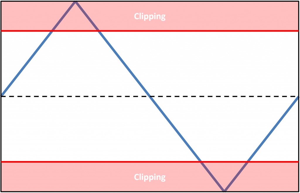
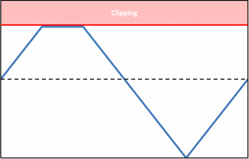
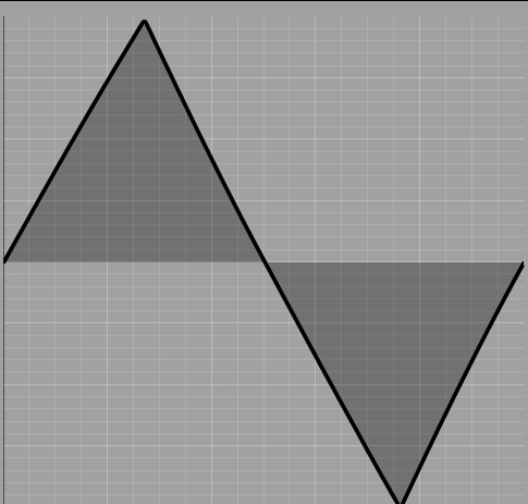
At the beginning of my “life with the A-116” I assumed that the clipping in the A-116 works like an amplifier. So simply cuts off the peaks that – in the positive as well as in the negative area – exceed a certain threshold. Like this:
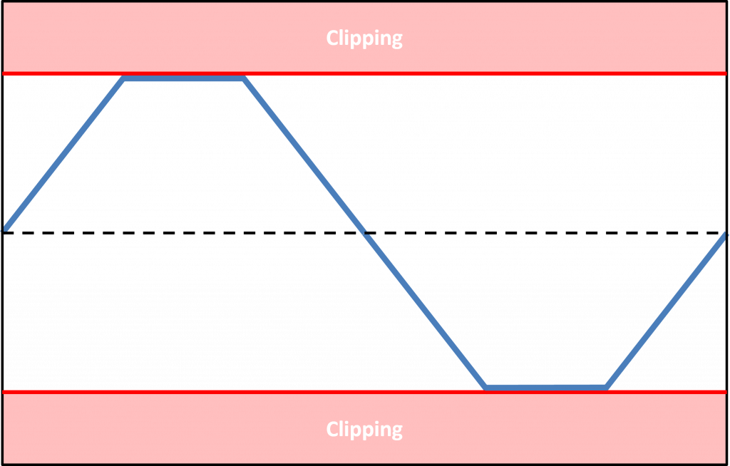
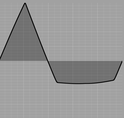
But the clipping does not work symmetrically here, but only cuts off the part of the oscillation that is actually “larger” than the threshold value:
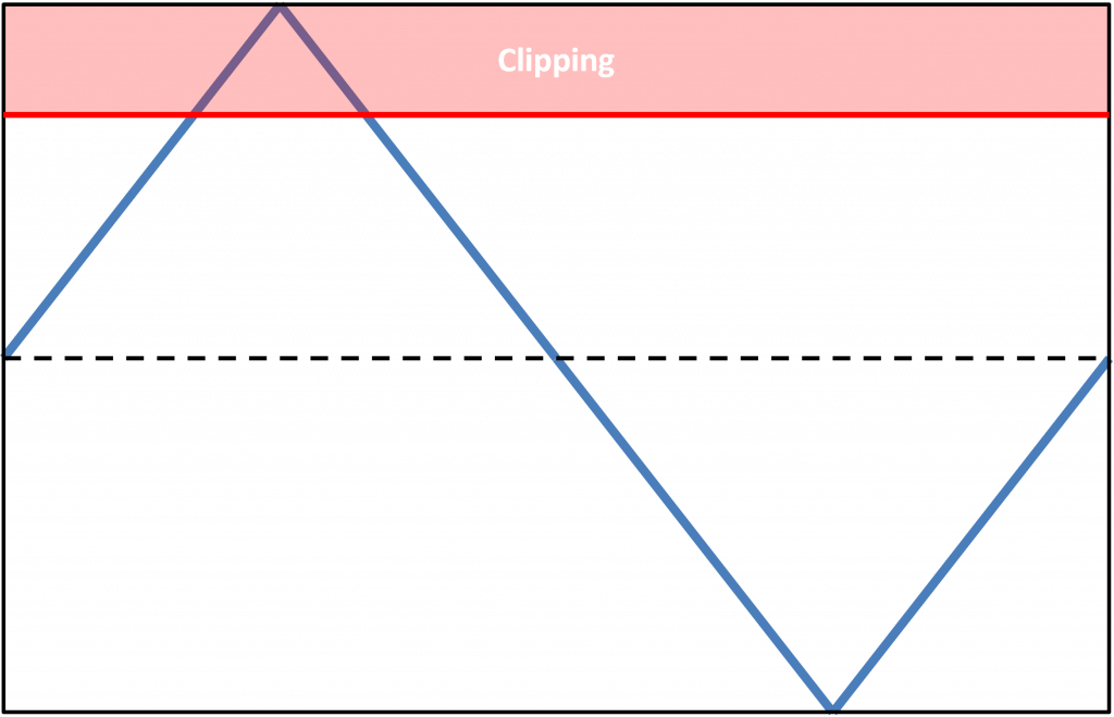
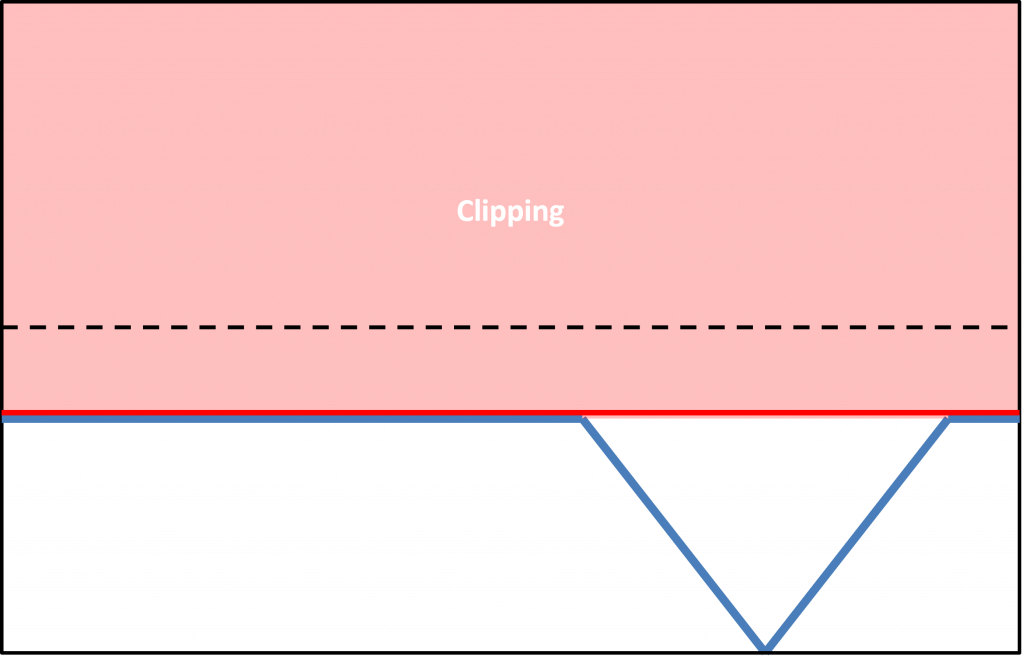
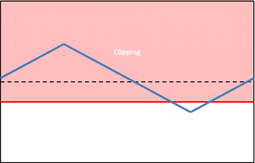
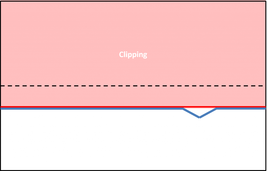
Incidentally, this form of clipping ensures that the initial amplification of the input signal does not necessarily lead to greater distortion. As soon as the clipping level is below the zero line, a larger part of the waveform is clipped than with high gain, especially with low gain.
Simple distortion
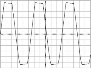
However, the A-116 also has the symmetrical clipping described above, and that makes operation a bit more complex than one would expect from the simple functional principle. The “Audio In” input of the module is relatively sensitive, so that even with a conventional VCO as the input signal, it turns into a hard – symmetrical – distortion with a slightly higher “Lev.” control. Here the “Clipping Lev.” control, which is then responsible for the asymmetrical clipping, is still in the neutral (upper) range.
Otherwise, the A-116 is actually built quite simply: The symmetrical and asymmetrical clipping just described is supplemented with a polarizer, which is referred to here as “Symmetry”.
For this purpose, parallel to the clipping, the original signal is amplified (or actually attenuated) with a polarizer in the range from -1 to +1. Both signals pre-processed in this way are finally mixed together, if necessary everything is also voltage-controlled. This makes it good to use if you want to distort a signal “on the fly”. Due to the special clipping characteristics, however, the results are often difficult to predict, so the module can be operated more easily by “intuitive screwing” than by precise prior planning.
Clipping for modulation signals
Wave shapers are also good for increasing the complexity of modulation signals.
Sound examples
-
A-116 / How the clipping “actually” works
Despite all the theory, I always found the A-116 to be quite unpredictable, the results usually sounded different – and looked different on the oscilloscope – than I had thought.
So go about it very stubbornly and “unmusically”. An A-111-1 provides a triangle wave that goes straight into the A-116. Still completely undistorted at a medium input level, the peaks are “cut off” symmetrically from a certain level.
A triangle wave from an A-111-1, still undistorted. 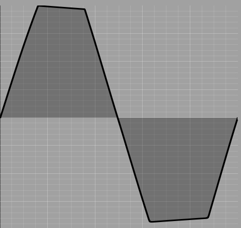
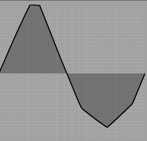
The same vibration is cut off symmetrically when the “Lev.” controller is increased. “Sym” is on a medium level, i.e. the original signal is not yet mixed in again – positive or negative – and the clipping level for the asymmetrical clipping is still at maximum.
The original triangle wave, undistorted. Slowly increasing the “Lev.” controller results in symmetrical distortion. We’ll go back to an undistorted input signal and use the “Clipping Lev.” controller. This cuts the signal asymmetrically, i.e. only one side of the waveform changes. Since the module outputs an inverted signal, we see the effect on the oscilloscope on the lower side of the oscillation. Of course, this inversion is not audible.
The clipping is asymmetrical. 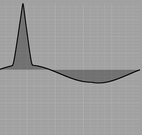
As the level drops further, the result becomes increasingly “strange”… 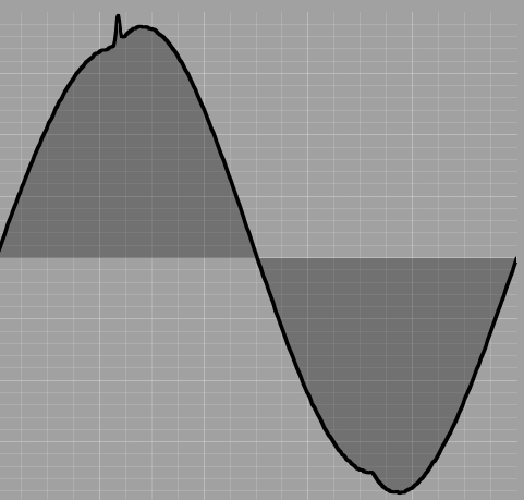
… until we finally arrive at an almost pure sine wave. Increasing (asymmetric) clipping of our triangle wave. Now we add the original waveform – normal or inverted – to our clipping signal. With a corresponding overall level, symmetrical clipping also occurs again.
Asymmetrically clipped signal with a small portion of the original signal (not inverted). 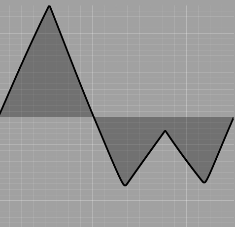
Asymmetrically clipped signal with a small portion of the original signal (inverted). 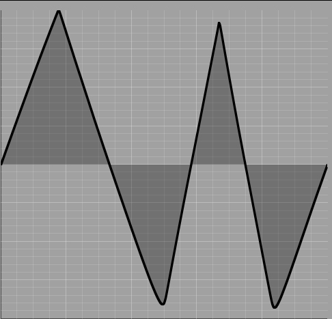
Asymmetrically clipped signal with a significant portion of the original signal (inverted). The original signal (positive and later inverted) is added to the clipping signal.
Technical specifications
| Width | 8 HP |
| Depth | 40 mm |
| Power requirements | 20 mA (+12V) / -20 mA (-12V) |